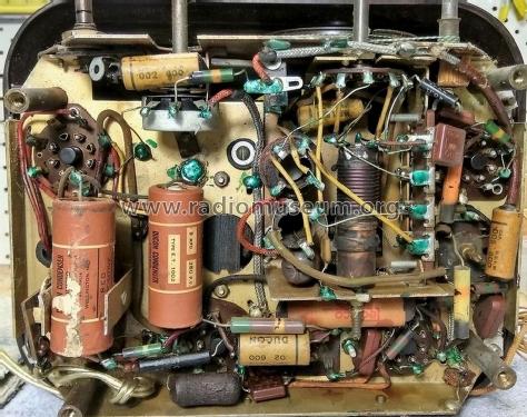
Beehive 11-4FZ
Kriesler Radio Company; Newtown (Sydney)
- País
- Australia
- Fabricante / Marca
- Kriesler Radio Company; Newtown (Sydney)
- Año
- 1946–1948

- Categoría
- Radio - o Sintonizador pasado WW2
- Radiomuseum.org ID
- 205442


Haga clic en la miniatura esquemática para solicitarlo como documento gratuito.
- Numero de valvulas
- 4
- Principio principal
- Superheterodino en general; ZF/IF 455 kHz; 2 Etapas de AF; Reflex
- Número de circuitos sintonía
- 6 Circuíto(s) AM
- Gama de ondas
- OM y OC
- Tensión de funcionamiento
- Red: Corriente alterna (CA, Inglés = AC) / 220; 240 Volt
- Altavoz
- Altavoz dinámico (de imán permanente) / Ø 5 inch = 12.7 cm
- Material
- Bakelita
- de Radiomuseum.org
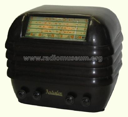
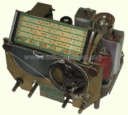
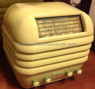
- Modelo: Beehive 11-4FZ - Kriesler Radio Company;
- Forma
- Sobremesa de tamaño mediano sin botonera <= 35 cm. (Incluso portables pero sólo con alimantación por red).
- Ancho, altura, profundidad
- 250 x 220 x 210 mm / 9.8 x 8.7 x 8.3 inch
- Anotaciones
-
Kriesler advertised this set & other post-war models as a "Sealed Radio". Solder joints were marked to prevent unauthorised servicing & tampering.
Walnut Bakelite cabinet. Also available in various colours for 1 Guinea (£1/1/-) extra. Price in WA for standard Walnut model, £19/8/6.
There are 36 variants of this model:
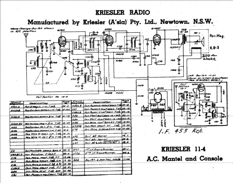
- CIRCUIT: As on 11-4 circuit but with the following alterations:- (Note: Enclosed diagram in lower right hand corner of sheet does not apply).
- Tone control (0.5 Megohm Potentiometer) replaced by 2 position, 0.02 μF 600v. condenser (C95) and 0.5 Megohm ½ watt resistor (R117). Disconnect lead from centre lug of potentiometer, and wire it to stationary contact of switch. Earth moving arm of switch. Replace potentiometer with fixed resistor.
- Power transformer changed from 18-27 to 18-1.
- 6J8G valve replaced by ECH35 converter.
- R103A (15,000 Ω) was replaced by R153A (40,000 Ω), R136 (30,000 Ω) was replaced by R153B (40,000 Ω).
- R139 (50 Ω) was replaced by R157 (20 Ω).
- 5Y3G valve replaced by 6X5GT rectifier, (6X5GT heater connected to 6.3v winding on transformer.
- Speaker 70-1 was replaced by speaker 70-8.
- H.T. choke (28-3) to replace field of 70-1 speaker.
- COIL KIT: Part No. 15-2 (S.C. Tuning Condenser).
- DIAL GLASSES: Part No. 50-12 (Principle section). Part No. 50-25 (Rear glass).
- SPEAKER: Part No. 70-8 (5" Permanent magnet type).
- OUTPUT TRANSFORMER: Part No. 18-26.
- POWER TRANSFORMER: Part No. 18-32 (H.T.: 250v each side of centre tap).
- NOTE: Power transformers 18-32 & 18-6 are interchangable. When 18-32 is used a 400 Ω bias resistor is used. When 18-6 is used a 250 Ω bias resistor is used.
- Precio durante el primer año
- 18.90 AUS £
- Referencia esquema
- Australian Official Radio Service Manual Vol. VI
- Documentación / Esquemas (1)
- - - Manufacturers Literature (Kriesler Technical Service Instructions.)
- Documentación / Esquemas (2)
- Australian Official Radio Service Manual AORSM (Volume 6, 1948, Page 262.)
- Autor
- Modelo creado por Stuart Irwin. Ver en "Modificar Ficha" los participantes posteriores.
- Otros modelos
-
Donde encontrará 901 modelos, 469 con imágenes y 439 con esquemas.
Ir al listado general de Kriesler Radio Company; Newtown (Sydney)
Colecciones
El modelo Beehive es parte de las colecciones de los siguientes miembros.