Beehive 11-4J Ch= 11-4
Kriesler Radio Company; Newtown (Sydney)
- País
- Australia
- Fabricante / Marca
- Kriesler Radio Company; Newtown (Sydney)
- Año
- 1946–1948
- Categoría
- Radio - o Sintonizador pasado WW2
- Radiomuseum.org ID
- 297575

Haga clic en la miniatura esquemática para solicitarlo como documento gratuito.
- Numero de valvulas
- 4
- Principio principal
- Superheterodino en general; ZF/IF 455 kHz; Reflex
- Gama de ondas
- OM y OC
- Tensión de funcionamiento
- Red: Corriente alterna (CA, Inglés = AC) / 220-240 Volt
- Altavoz
- Altavoz dinámico (de imán permanente)
- Material
- Bakelita
- de Radiomuseum.org
- Modelo: Beehive 11-4J Ch= 11-4 - Kriesler Radio Company;
- Forma
- Sobremesa de tamaño mediano sin botonera <= 35 cm. (Incluso portables pero sólo con alimantación por red).
- Anotaciones
-
Kriesler advertised this set & other post-war models as a "Sealed Radio". Solder joints were marked to prevent unauthorised servicing & tampering.
Walnut Bakelite cabinet. Also available in various colours for 1 Guinea (£1/1/-) extra. Price in WA for standard Walnut model, £19/8/6.
There are 36 variants of this model:
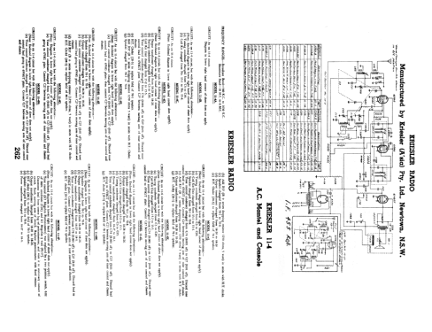
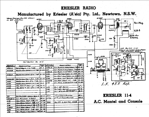
- CIRCUIT: As on 11-4 circuit, but with the following alterations:- (Note: Enclosed diagram in lower right hand corner does apply).
- Tuning condenser changed from C3 to C95.
- Coil Kit Unit changed from 15-1 to 15-4.
- Speaker changed from 70-1 to 70-8.
- Tone control condenser changed from C74 (0.001 μF) to C27 (0.01 μF). Discard tone control lead to 6V6GT plate. Connect C27 between moving arm of tone control and chassis.
- Add R37 (B + series dropping resistor 1250 Ω, 5 watt) in series with H.T. choke.
- Output transformer changes from from 18-28 to 18-26.
- H.T. Choke (28-3) to replace field of 70-1 speaker.
- COIL KIT: Part No. 15-4 (AWA Tuning Condenser).
- DIAL GLASSES: Part No. 50-10 (Country stations). Part No. 50-11 (Local stations).
- SPEAKER: Part No. 70-8 (5" Permanent magnet type).
- OUTPUT TRANSFORMER: Part No. 18-26.
- POWER TRANSFORMER: Part No. 18-27 (H.T.: 325v each side of centre tap).
PROCEDURE FOR REMOVING CHASSIS FROM CABINET:
- Remove knobs.
- Invert receiver.
- Remove base by breaking seal and unscrewing 4 x 3/16" screws in base of cabinet.
- Remove 4 x 3/16" nuts, situated in the inside corners of the chassis.
- Lay receiver on its back with spindles facing upwards.
- Place one hand each side the of chassis. With the forefingers, exert a downward pressure on the front panel, at the same time withdrawing the chassis from the cabinet.
CHASSIS NUMBERS:
Every receiver that leaves the Kriesler factory is given two chassis numbers.
The "Production" chassis number is stamped on a card. The card is riveted to the main chassis in such a location that the number is able to be read without removing the chassis from the cabinet. The "Production" chassis number is the number that should be quoted, together with the model number, when making enquiries.
The second chassis number (Prefix "0") is stamped into the metal chassis to provide a permanent record.
Both the abovementioned chassis numbers are recorded at the factory.
- Precio durante el primer año
- 18.90 AUS £
- Documentación / Esquemas (1)
- - - Manufacturers Literature (Kriesler Technical Service Instructions.)
- Documentación / Esquemas (2)
- Australian Official Radio Service Manual AORSM (Volume 5, 1947, Page 188 & Volume 6, 1948, Page 262.)
- Autor
- Modelo creado por Martin Kent. Ver en "Modificar Ficha" los participantes posteriores.
- Otros modelos
-
Donde encontrará 902 modelos, 471 con imágenes y 439 con esquemas.
Ir al listado general de Kriesler Radio Company; Newtown (Sydney)