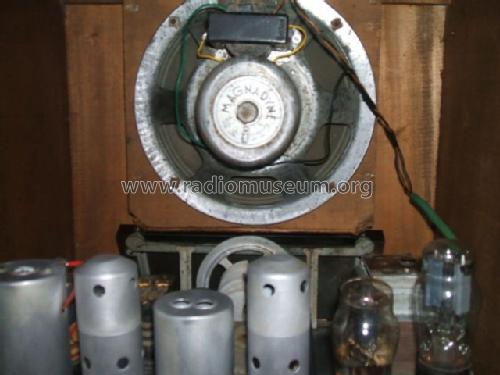
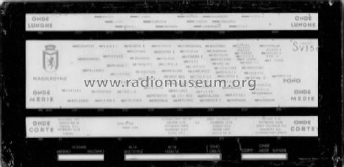
- Land
- Italien / Italy
- Hersteller / Marke
- Magnadyne Radio; Torino
- Jahr
- 1936/1937
- Kategorie
- Rundfunkempfänger (Radio - oder Tuner nach WW2)
- Radiomuseum.org ID
- 30595
Klicken Sie auf den Schaltplanausschnitt, um diesen kostenlos als Dokument anzufordern.
- Anzahl Röhren
- 5
- Hauptprinzip
- Superhet allgemein; ZF/IF 362.5 kHz
- Wellenbereiche
- Langwelle, Mittelwelle und Kurzwelle.
- Betriebsart / Volt
- Wechselstromspeisung / 110; 125; 145; 155; 175; 250 Volt
- Lautsprecher
- Dynamischer LS, mit Erregerspule (elektrodynamisch) / Ø 20 cm = 7.9 inch
- Material
- Gerät mit Holzgehäuse
- von Radiomuseum.org
- Modell: S35 - Magnadyne Radio; Torino
- Form
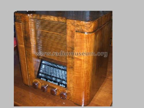
- Tischgerät, Hochformat (höher als quadratisch, schlicht, keine Kathedrale).
- Abmessungen (BHT)
- 420 x 420 x 300 mm / 16.5 x 16.5 x 11.8 inch
- Originalpreis
- 890.00 ITL
- Datenherkunft
- Guida Pratica Antique Radio III (2000)
- Literaturnachweis
- Catalogo Magnadyne 1937
- Literatur/Schema (1)
- Il Radio Libro (E.D. Ravalico) Edizioni Hoepli
- Literatur/Schema (2)
- -- Schematic (La Riparazione degli Apparecchi Radio, Delforno - Colciago, Italy 1941)
- Autor
- Modellseite von Alessandro De Poi angelegt. Siehe bei "Änderungsvorschlag" für weitere Mitarbeit.
- Weitere Modelle
-
Hier finden Sie 356 Modelle, davon 275 mit Bildern und 256 mit Schaltbildern.
Alle gelisteten Radios usw. von Magnadyne Radio; Torino
Sammlungen
Das Modell befindet sich in den Sammlungen folgender Mitglieder.
Forumsbeiträge zum Modell: Magnadyne Radio;: S35
Threads: 1 | Posts: 1
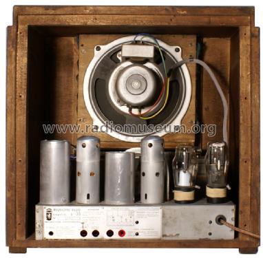
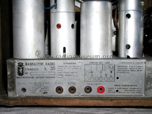
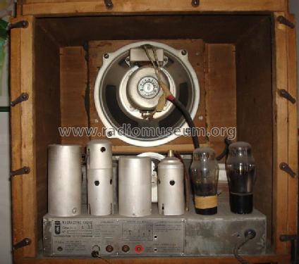
The Magnadyne S35 was one of the less expensive models of this producer (890 Italian lire against the 1090 lire of the SV10 and the 1190 lire of the SV15) and lacked the sophisticated variable selectivity control of the more expensive sets; this allowed the use of a cheaper version of the second I.F. transformer and a simpler mechanical layout. All other components, however, were the same used in top models and the overall performance was quite similar. The S35 used the American line of tubes 6A7, 6D6, 75, 42 and 80. The unit described in this note was essentially untouched so that the actual circuit was the expected one (see however the subsequent observation concerning the common error present in most S35 diagrams). The points that could be of some interest in restoring this set are the following:
1) Wiring. Most of the original wiring was based on rubber-coated wires with different colors and must be substituted. See “Restoring the Magnadyne SV3” for more details and possible philological substitutions.
2) Capacitors. Looking inside the chassis of the S35, the first impression is that many capacitors are missing. This little mystery is solved by removing the breadboard shown in Figure 1; the missing capacitors are allocated in a single container on its back.

Figure 1 – S35 breadboard (front and back of the restored unit)
Since the leakage of two capacitors was excessive, all capacitors have been substituted; opening the container it is possible to observe that one of the capacitors, differently from what could be expected from the label, is larger as shown in Figure 2 (in fact its capacity was 0.2 µF instead than 0.1 µF).

Figure 2 – The capacitor box under the breadbord
Also the two electrolytic capacitors (6 µF) are of the box type.
3) Mica capacitors. The mica capacitors used in the S35 were produced by Ducati and are contained in robust metal cases (one of them can be seen in Figure 1). Their stability is excellent and most of them are still inside their nominal tolerance range. No substitutions are usually necessary.
4) I.F. transformers. The first I.F. transformer is equal to those of top-line sets (see “Restoring the Magnadyne SV3”) while the second one has a more simple and standard construction.
5) Tuning mechanism. The S35 uses the same mechanism, based on a rubber sleeve that engages a cogwheel connected by means of a drive cord to the tuning capacitor. The substitution of the rubber sleeve could be necessary (it was not the case in this set); see “Restoring the Magnadyne SV3” for more details and a picture.
6) Beware of diagram errors. Not many versions of the S35 diagram are available and all the diagrams in my knowledge are affected (with the exception of the corrected one that I have uploaded) by the exchange of two connections that, fortunately, does not damage the set but almost mutes it. More precisely, look at the portion of circuit reported in Figure 3 that shows the wrong diagram; the connections denoted as “Diode 75” and “Grid 75” must, in fact, be inverted.
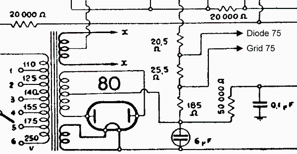
Figure 3 – Wrong diagram of the S35
7) Alignment. The same as for the SV3.
8) I.F. channel response. After a careful alignment of the I.F. channel (center frequency 362.5 KHz), its frequency response has been measured by means of the procedure described in “Measuring the I.F. response in AM receivers”. The results are reported in Figure 4 where the measured response is compared with the response of the SV3 at maximal and minimal bandwidth settings. It can be observed that the set is perfectly aligned and that the response falls mainly in the middle of the extreme responses of the SV3; the overall shape of the SV3 responses is, however, definitely better.

Figure 4 – I.F. response of the S35 (blue) compared with the response of the SV3 (red) at wide and narrow bandwidth settings.

Figure 5 – The restored S35
Roberto Guidorzi, 17.Dec.12


