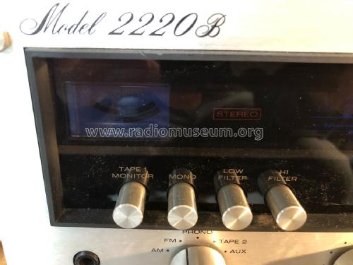
Stereophonic Receiver 2220B
Marantz (Sound United LLC); Vista, CA
- País
- Estados Unidos
- Fabricante / Marca
- Marantz (Sound United LLC); Vista, CA
- Año
- 1975–1977 ?
- Categoría
- Radio - o Sintonizador pasado WW2
- Radiomuseum.org ID
- 280177
- Numero de transistores
- Hay semiconductores.
- Principio principal
- Superheterodino en general; ZF/IF 455/10700 kHz
- Gama de ondas
- OM y FM
- Especialidades
- Hi-Fi equipment
- Tensión de funcionamiento
- Red: Corriente alterna (CA, Inglés = AC) / 110; 120; 220; 240 Volt
- Altavoz
- - Este modelo usa altavoz exterior (1 o más).
- Potencia de salida
- 40 W (undistorted)
- Material
- Metálico
- de Radiomuseum.org
- Modelo: Stereophonic Receiver 2220B - Marantz Sound United LLC;
- Forma
- Unidad para estanteria.
- Ancho, altura, profundidad
- 17.375 x 5.375 x 14 inch / 441 x 137 x 356 mm
- Anotaciones
-
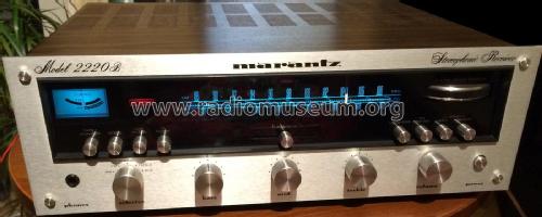
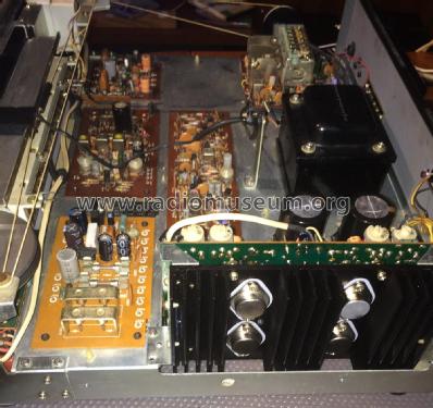
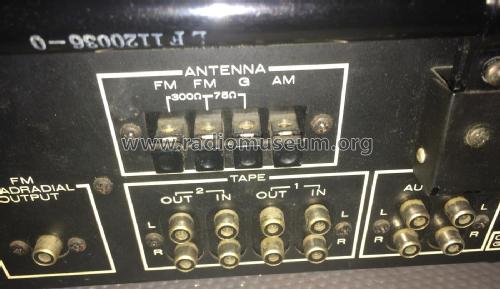
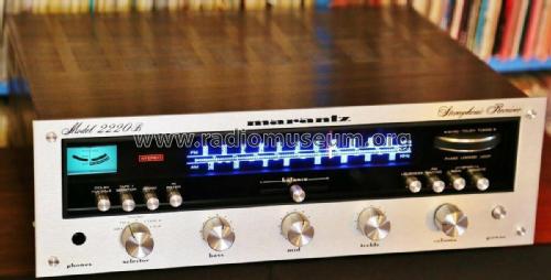
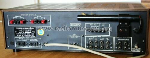
A hi-fi stereo receiver with an AM/FM stereo tuner with analogue dial and an integrated amplifier with power output of 2 x 20 watts RMS into 4 ohms or 8 ohms, housed in a metal case (wooden case optional). With an AM/FM Tuning meter, Gyro Touch tuning, rotary controls for Bass, Mid, Treble and Volume, slider Balance control, rotary Selector switch (AM, FM, Phono, Tape2, Aux), push button switches for Tape1 Monitor, Mono, Low Filter (not on US model), Hi Filter, Loudness, FM Muting, Speakers Main and Remote, jack for headphones and on the US model, a 25µS Dolby FM switch. On the back, an AM ferrite rod antenna, terminals for AM and FM antennae, RCA phono sockets for input phono (MM) and Aux, for input/output for 2 Tapes and for FM Quadradial output, terminals for 2 pairs of loudspeakers, switched and unswitched AC outlets.
Specification Audio Section Rated Power Output (Continuous Average
per Channel, All Channels Driven)
20Hz-20kHz, THD 0.5%Into 4Ω
Into 8Ω
Into 16Ω20 Watts
20 Watts
10 WattsDynamic range
(phono input to tape recording output)96dB IM Distortion (SMPTE), at rated power 0.9% Total Harmonic Distortion, at rated power 0.5% Max. Power Bandwidth (IHF) for 0.5% THD 10Hz-50kHz Damping Factor (8Ω) > 20 Frequency Response through phono 2.0dB Input Sensitivity (for 15W at 8Ω) Line
Phono (1kHz)180mV
1.8mVInput Impedance Line
Phono100kΩ
47kΩChannel Separation 20Hz-10kHz 30dB Min. FM Section IHF Usable Sensitivity 2.5µV Selectivity 50dB Noise Quieting -70 dB at 1.000µV THD, 400 Hz, 100% Mod 0.3% Max. Frequency Response 50Hz-15KHz ±1dB Stereo Separation 1kHz 40dB Sub Carrier (38kHz) Suppression 60dB AM Section Sensitivity 25µV Versions/Power requirements
120V AC 50/60Hz (US model)
110/120/220/240V AC 50/60Hz switchable internallyPower consumption: 130 watts
See also the Marantz 2220BL Stereophonic Receiver which additionally has LW and also similar to the earlier Marantz 2220 Stereophonic Receiver.
Designed in USA, Produced in Japan.
- Peso neto
- 23 lb 0 oz (23 lb) / 10.442 kg
- Documentación / Esquemas (1)
- Photofact Folder, Howard W. SAMS (SAMS # MHF-91)
- Documentación / Esquemas (2)
- -- Original-techn. papers.
- Documentación / Esquemas (3)
- - - Manufacturers Literature (Service Manual Marantz 2220B)
- Documentación / Esquemas (4)
- - - Manufacturers Literature (Handbook of Instructions Marantz 2220B)
- Autor
- Modelo creado por Frank Annweiler. Ver en "Modificar Ficha" los participantes posteriores.
- Otros modelos
-
Donde encontrará 569 modelos, 560 con imágenes y 92 con esquemas.
Ir al listado general de Marantz (Sound United LLC); Vista, CA
Colecciones
El modelo Stereophonic Receiver es parte de las colecciones de los siguientes miembros.
Contribuciones en el Foro acerca de este modelo: Marantz Sound United: Stereophonic Receiver 2220B
Hilos: 1 | Mensajes: 1
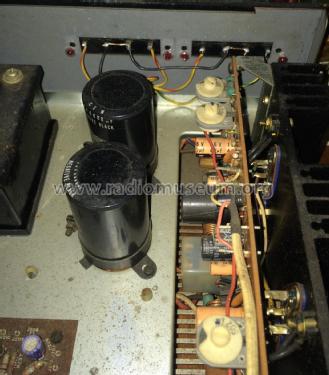
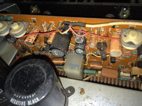
Zum diesem Marantz-Modell 2220B ist im Internet leicht das Marantz-ServiceManual zu finden. Leider hat dieses Fehler:
Schaltplan:
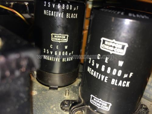
Beim Ladekondensator C004 ist die Polung falsch herum angegeben. Das + Symbol muss unten sein.
Abgleichanweisung:
12. Power Supply Adjustment:
Für den Abgleich des Ruhestroms der Endstufen ist hier angegeben mit einem Voltmeter zwischen J712(+) und J718(-) zu messen und mit R733 auf 20mV einzustellen. Für den anderen Kanal soll gleiches zwischen J713(+) und J719(-) gemessen werden und mit R734 eingestellt werden.
Stattdessen ist folgendes Vorgehen richtig:
Zwischen J714(+) und J716(-) messen und mit R733 20mV einstellen. Für den anderen Kanal zwischen J715(+) und J717(-) messen und mit R734 20mV einstellen.
Der beim Abgleich des virtuellen Nullpunktes kann der Abgleichanweisung gefolgt werden.
Frank Annweiler, 06.Apr.16
