Wireless Set No.12 Sender
MILITARY U.K. (different makers for same model)
- Land
- Grossbritannien (UK)
- Hersteller / Marke
- MILITARY U.K. (different makers for same model)
- Jahr
- 1941–1944 ?
- Kategorie
- Militär-Sender
- Radiomuseum.org ID
- 271818
Klicken Sie auf den Schaltplanausschnitt, um diesen kostenlos als Dokument anzufordern.
- Anzahl Röhren
- 9
- Hauptprinzip
- Sender
- Wellenbereiche
- Wellen in den Bemerkungen.
- Betriebsart / Volt
- Netzstrom-Gerät (Art nicht bekannt) / 100-250 Volt
- Lautsprecher
- - Für Kopfhörer oder NF-Verstärker
- Material
- Metallausführung
- von Radiomuseum.org
- Modell: Wireless Set No.12 Sender - MILITARY U.K. different makers
- Form
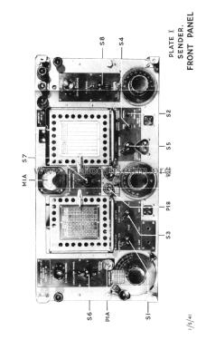
- Schweres Gerät für Militär oder Industrie (Boatanchor > 20 kg).
- Abmessungen (BHT)
- 24 x 12.5 x 17.5 inch / 610 x 318 x 445 mm
- Bemerkung
-
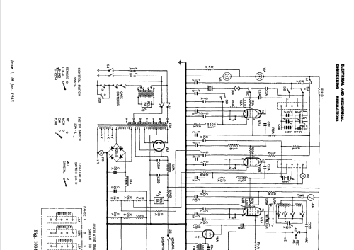
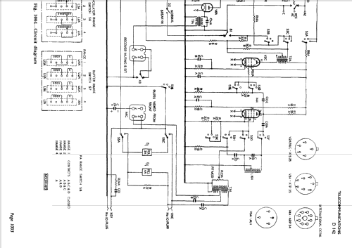
An HF transmitter used by the British Army in larger vehicles from 1940 onwards, with the accompanying R107 HF receiver. It produces about 25W in CW mode, and 7W in AM/RT mode. There are two models of the equipment: the Mk.I runs on line frequencies of 45 - 65c/s, and the Mk.II on line frequencies of 45 to 500c/s. Line voltages are 100 - 250V for both models.
The frequency range is 1.2Mc/s to 17.5Mc/s in four overlapping bands. As well as CW and R/T (AM) modes, it includes a MCW mode to send Morse to receivers with no BFO.
The main stages are (1) an oscillator, which can be crystal controlled or variable frequency running at half the output frequency, (2) a separately tuned multiplier/buffer amplifier, (3) a Class C power amplifier with a parallel tuned circuit output using a variable tapped inductor to match aerial impedances of 100 - 600 ohms, (4) a microphone pre-amplifier and 900c/s audio oscillator in MCW mode, (5) a modulator stage which is transformer coupled to suppressor grid of the PA valve, and (6) a rectifier to produce sidetone directly from the modulated RF output.
This is one of the first British transmitters to improve on the older MOPA configuration by introducing an intermediate buffer stage, which is not there to increase the drive to the PA, but rather to isolate the VFO from the pulling effects of tuning the PA. This feature, along with a stabilised HT supply to the VFO helped limit drift to a maximum of 3kc/s at 10Mc/s output frequency (300ppm).
Accompanying equipment includes the R107 receiver, Aerial Coupling Units Type F and Type H, and Remote Control Unit Type C.
- Nettogewicht
- 134 lb (134 lb 0 oz) / 60.836 kg
- Literaturnachweis
- Wireless for the Warrior; L.Meulstee (Volume 1, Chapter WS12)
- Literatur/Schema (1)
- -- Original-techn. papers. (EMER Tels D142 and D144, Jan and Feb 1945)
- Literatur/Schema (2)
- -- Original-techn. papers. (Wireless Set No.12 Mk.II General Description, Working Instructions, Aerials and Maintenance.)
- Autor
- Modellseite von Richard Hankins angelegt. Siehe bei "Änderungsvorschlag" für weitere Mitarbeit.
- Weitere Modelle
-
Hier finden Sie 152 Modelle, davon 120 mit Bildern und 48 mit Schaltbildern.
Alle gelisteten Radios usw. von MILITARY U.K. (different makers for same model)
Sammlungen
Das Modell Wireless Set No.12 Sender befindet sich in den Sammlungen folgender Mitglieder.