Oscilloscope - Test Set TS-182/UP
MILITARY U.S. (different makers for same model)
- Country
- United States of America (USA)
- Manufacturer / Brand
- MILITARY U.S. (different makers for same model)
- Year
- 1945
- Category
- Service- or Lab Equipment
- Radiomuseum.org ID
- 206075
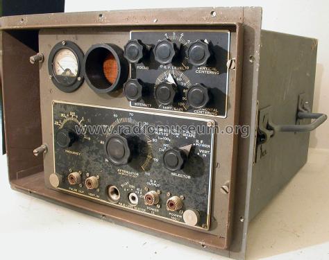
USA Military TS-182/UP test set front view
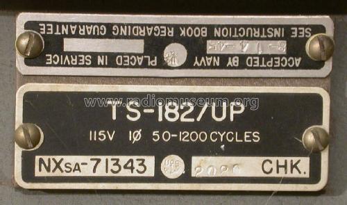
USA Military TS-182/UP test set label
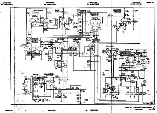
Click on the schematic thumbnail to request the schematic as a free document.
- Number of Tubes
- 11
- Wave bands
- Wave Bands given in the notes.
- Power type and voltage
- Alternating Current supply (AC) / 115 Volt
- Loudspeaker
- - - No sound reproduction output.
- Material
- Metal case
- from Radiomuseum.org
- Model: Oscilloscope - Test Set TS-182/UP - MILITARY U.S. different makers
- Shape
- Boatanchor (heavy military or commercial set >20 kg).
- Notes
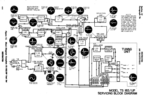
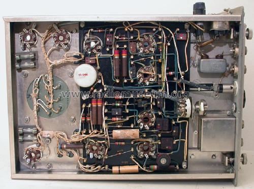
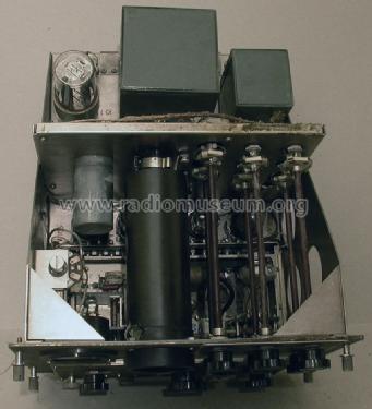
- This equipment operates from a 115 volt 50 - 120 Hz mains supply and is primarily intended for checking the sensitivity of receivers and the power output of transmitters intended to receive and transmit pulse-modulated signals. The equipment operates over a frequency range of 150 to 240 MHz and may be used, in addition, to roughly check the frequency of operation of receiving equipment operating within this range. The unit is further suitable for displaying with good fidelity the actual pulse shape of short r-f pulses (from 2 to 200 microseconds long) on the built-in cathode ray oscilloscope and can, therefore, also serve as a means for comparing the length of r-f pulses. The unit is capable of making the following measurements: (1) Receiver sensitivity, (2) R-F pulse power up to 3000 peak watts, (3) Transponder Sensitivity and Power Output, (4) R-F pulse shapes and durations, (5) Video pulse shapes and durations. This unit is suited for supplying pulse-modulated r-f voltages of a known magnitude to any receiver intended to receive pulse-modulated signals, capable of operating within the frequency band of 150 to 240 MHz and having an input impedance of approximately 50 ohms. In addition, the receiver under test must be capable of delivering a video output signal of at least one volt peak before any limiting begins. Demonstrating the simplicity of design also present in the TS-148 test set, this TS-182 unit has sophisticated circuits (for its day: 1945) with a minimum of component count. For instance, a "delay one-kick multivibrator" is incorporated to delay the r-f pulse generated by the r-f oscillator by about 20 microseconds following the beginning of the oscilloscope sweep, so that any indication appearing on the oscilloscope of this equipment will likewise appear a short distance from the left of the sweep where it can be more readily observed. The attached schematic further demonstrates this spartan, yet highly functional design. Using a tube count of only eleven devices, the TS-182 test set includes an oscillator for generating the signals then measured after return from the device under test to both a meter and oscilloscope data display combination.
- Net weight (2.2 lb = 1 kg)
- 49 lb (49 lb 0 oz) / 22.246 kg
- Literature/Schematics (3)
- -- Schematic
- Author
- Model page created by Hank Kaczmarski. See "Data change" for further contributors.
- Other Models
-
Here you find 401 models, 353 with images and 210 with schematics for wireless sets etc. In French: TSF for Télégraphie sans fil.
All listed radios etc. from MILITARY U.S. (different makers for same model)
Collections
The model Oscilloscope - Test Set is part of the collections of the following members.