62C1 Ch= HS-299
Motorola Inc. (ex Galvin Mfg.Co. Chicago); Schaumburg (IL)
- Pays
- Etats-Unis
- Fabricant / Marque
- Motorola Inc. (ex Galvin Mfg.Co. Chicago); Schaumburg (IL)
- Année
- 1951/1952
- Catégorie
- Radio - ou tuner d'après la guerre 1939-45
- Radiomuseum.org ID
- 49102
Cliquez sur la vignette du schéma pour le demander en tant que document gratuit.
- No. de tubes
- 6
- Principe général
- Super hétérodyne avec étage HF; FI/IF 455 kHz; 2 Etage(s) BF
- Circuits accordés
- 7 Circuits MA (AM)
- Gammes d'ondes
- PO uniquement
- Tension / type courant
- Alimentation Courant Alternatif (CA) / 117 Volt
- Haut-parleur
- HP dynamique à aimant permanent + bobine mobile / Ø 4 inch = 10.2 cm
- Matière
- Plastique moderne (pas de bakélite, ni de catalin)
- De Radiomuseum.org
- Modèle: 62C1 Ch= HS-299 - Motorola Inc. ex Galvin Mfg.Co
- Forme
- Modèle de table avec réveil ou horloge
- Remarques
-
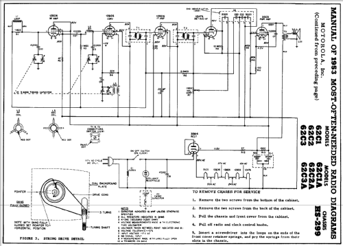
Color= Walnut. RF preamp is 12BD6 pentode wired as a cathode follower. Voltage gain from this stage is obtained by LC impedance transformation. The voltage gain is approximately the same as the loaded LC Q. Cathode follower circuits are very rare in RF or IF circuits.
The Motorola model 62C is available in different colors: model 62C1 in Walnut, model 62C2 in Ivory and model 62C3 in Green.
- Source extérieure
- Ernst Erb
- Source du schéma
- Beitman Radio Diagrams Vol. 13, 1953
- Schémathèque (1)
- Rider's Perpetual, Volume 23 (last) = covering up to 1954
- Schémathèque (3)
- Motorola Folder No. 3301 for 1952.
- D'autres Modèles
-
Vous pourrez trouver sous ce lien 4607 modèles d'appareils, 2964 avec des images et 4107 avec des schémas.
Tous les appareils de Motorola Inc. (ex Galvin Mfg.Co. Chicago); Schaumburg (IL)
Contributions du forum pour ce modèle: Motorola Inc. ex: 62C1 Ch= HS-299
Discussions: 1 | Publications: 2
Dear Radiophiles,
As I was reading a very interesting thread about the use of RC-coupled high frequency amplifiers, I was reminded of the only cathode follower RF circuit I have ever seen. This post was revised and moved here from the RC-coupled thread on Aug 5th 2009.
A 12BD6 remote cutoff pentode was used as the RF cathode follower preamp for the Motorola 62C1 chassis HS299. However, the cathode follower is loaded with a tuned series resonant RF circuit that steps up the voltage with a gain that is approximately the same as the net Q of the series combination of 47 Ohm driven by the cathode, L and C. This tuned circuit serves as the second RF tuned circuit and is under control of a 3-gang tuning capacitor. Keep in mind that the 12BD6 only has 2mS of transconductance, so there is an immediate attenuation of 1/10 from it's control grid to the 47 Ohm load at the cathode.
A while back, I wondered when the cathode follower was first used. I also thought that it could have been used very effectively during the triode era in the 1920's as an alternative to Neutralization of Miller capacitance.
Replacing the RF common cathode stages with RF common plate stages (another way of saying cathode follower stages) would have been done with the same number of triodes. The signal would enter the grid of stage and exit through the cathode, which would be loaded by a lower impedance tap of the usual inter-stage coupling transformer.
Triodes from the 1920's had an intrinsic voltage gain mu, between 5 and 10, so a tap could be taken with fewer turns as compared to the plate drive point of a conventional common cathode circuit. One challenge here would be to handle the square law reduction in impedance on the order of 1/25 to 1/100 that would result in driving a tap that is one fifth to one tenth the original plate driving point.
But this impedance decrease could have been managed. The impedance at resonance for the tune circuits could well exceed 100k-Ohms. This means that the cathode would be loaded by 1k in the worst case. The filamentary triode transconductance usually around 1mS, which results in a cathode impedance of 1k Ohm, thus making this configuration feasable.
It should be noted that grounded cathode amplifiers have voltage gains that are the direct ratio of plate load resistance to cathode resistance (the inverse of transconductance)
Gain=Rplate/Rcathode;
while transformers have a voltage step up ratio (equivalent to voltage gain) that is the square root of the ratio of secondary to primary impedances.
Step-up-ratio=SQRT(Rsecondary/Rprimary)
This puts transformers at a clear disadvantage as a means to acchieve voltage gain; and they will never provide power gain. For example, a typical IF stage with the very common 12BA6 IF pentode, could easily achieve a stage voltage gain of 100. The gm of the 12BA6 is 4.4mS, and an IF transformer with an internal impedance in excess of 22.7K is easy to find. I have measured IF transformers with an internal resistive impedance at resonance between 100k and 400k.
If I took the 400k transformer and added a tap to provide a 1:100 step-up ratio, the impedance at the low tap would be 400k/(100^2)=40_Ohms. The 12BA6 cathode, as a follower, will have an impedance of 1/4.4mS=227_Ohms, so an attenuation of 40/(227+40)=0.15 would result if the 12BA6 stage were configured as a cathode follower, and the net voltage gain would be only 100*0.15=15.
A conclusion that could be drawn is that stages with voltage gains under 10 can be reasonably implemented with a cathode follower driving a step-up transformer.
A further thought is that an emitter follower can easily provide an output impedance under 40_Ohms with less than 1mA of emitter current. The drawback here, is that the input impedance at the base of the follower would be on the order of beta times the cathode impedance plus the cathode load. This puts the input impedance at the base around 100*(40+40)=8k.
------------------
Now back to a realizable triode stage gain under 10 in the 1920's.
The problem of driving power to the filamentary cathode is easily solved with a bifilar winding that would carry heater power, which was only 60mA for a UX199, but while twisted tightly, the wire pair would act as a single wire in the transformer primary load for the RF signal from the cathode.
A comparison of tuned cathode followers and tuned common cathode amplifiers can be found on a thread exploring the Rel Rival 351.
Another example of a modern design with a cathode follower as done by Gyula Kiss, who is a member of www.nvhr.nl. I extracted the following from an email exchange we had, and which I copied (cc:) Messrs Knoll and Rudolph:
---------------------------------
Dear Gyula,
Wow, what a beautiful single tube reflex superhet radio design!
The last time I saw something this elegant it was the front end of a 3 tube AM/FM Grundig Radio.
[snip]
An all-triode design without neutralization; it does not need any.
The front end Armstrong type of converting oscillator needs no neutralization, because the dominant oscillation mode sets the primary tube behavior.
The cathode follower IF stage is near and dear to me. It requires no neutralization either, because the plate is AC grounded. A few months ago, I was wondering why cathode followers were never used in RF stages of the 1920's triode era, to avoid neutralization of Miller capacitance. Even with filamentary tubes of the 1920's, a bifilar RF transformer primary could have been used with zero resistance for DC heating current, while offering a resonant impedance to the cathode.
Your cathode follower IF stage gets it's voltage gain from the step-up tuned circuit, and from the voltage doubling detector. [snip]
---------------------------------
I remember hearing from Ed Lyon in one of these email exchanges that a cathode follower circuit had been used as a driver in a transmitting circuit. Ed Lyon is the Editor of Radio Age, which is the newsletter of MAARC, Mid-Atlantic Antique Radio Club.
Did cathode followers ever play a role as gain stages in tuned amplifier or Tuned-Untuned-Tuned amplifier design?
Regards,
-Joe
Joe Sousa, 06.Aug.09


