Stereo Amplifier 7W
Mullard Wireless, London (see also Mullard Radio Valve)
- País
- Gran Bretaña (GB)
- Fabricante / Marca
- Mullard Wireless, London (see also Mullard Radio Valve)
- Año
- 1958
- Categoría
- Amplificador de audio o mezclador
- Radiomuseum.org ID
- 283539
From manufacturers litrature
Haga clic en la miniatura esquemática para solicitarlo como documento gratuito.
- Numero de valvulas
- 6
- Principio principal
- Amplificador de Audio
- Gama de ondas
- - no hay
- Tensión de funcionamiento
- Red: Corriente alterna (CA, Inglés = AC) / 200-250 Volt
- Altavoz
- - Este modelo usa altavoz exterior (1 o más).
- Potencia de salida
- 14 W (undistorted)
- Material
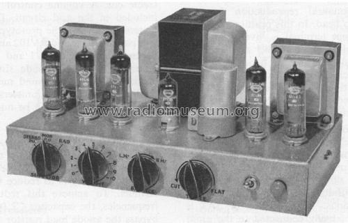
- Metálico con lámparas a la vista.
- de Radiomuseum.org
- Modelo: Stereo Amplifier 7W - Mullard Wireless, London see
- Forma
- Chasis (tambien de autoradio)
- Anotaciones
-
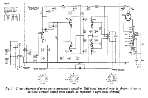
The circuit diagram drawn in Fig. 1 is for a high-quality, dual-channel amplifier designed principally for stereophonic reproduction but also providing facilities for monaural applications. Only one channel of the amplifier is drawn. The circuitry appearing between the dotted lines is for the left-hand channel: it should be duplicated for the right-hand channel. The circuitry drawn outside the dotted lines (the power supply, for example) is common to both channels.
The total complement of valves used in the amplifier consists of one double triode, type ECC83, four triode pentodes, type ECL82, and one full-wave rectifier, type EZ81. The double triode is shared between the two channels, one section of the valve being used in each channel for voltage amplification. Two of the ECL82 are used in each channel. The triode sections of these valves form a phase-splitting stage and the pentode sections are arranged as a push-pull output stage with distributed loading. The EZ81 forms a conventional power supply with resistance-capacitance smoothing, providing the h.t. for both channels.
The rated output-power reserve of each channel is 7W, at which level the total harmonic distortion is always better than 1.0 %. The low level of distortion is achieved by using 21dB of negative feedback, the feedback voltage being taken from the secondary winding of the output transformer in each channel to the cathode circuit of the corresponding input stage. The sensitivity of the circuit, even with this high value of feedback, is 120mV, which is ample for use with existing stereophonic crystal pick-up heads.
- Mencionado en
- - - Manufacturers Literature
- Autor
- Modelo creado por Gary Cowans. Ver en "Modificar Ficha" los participantes posteriores.
- Otros modelos
-
Donde encontrará 143 modelos, 117 con imágenes y 59 con esquemas.
Ir al listado general de Mullard Wireless, London (see also Mullard Radio Valve)