7501 Ch= 150
Olympic Radio & Television, Inc.; New York (NY)
- Country
- United States of America (USA)
- Manufacturer / Brand
- Olympic Radio & Television, Inc.; New York (NY)
- Year
- 1959 ?
- Category
- Broadcast Receiver - or past WW2 Tuner
- Radiomuseum.org ID
- 140047
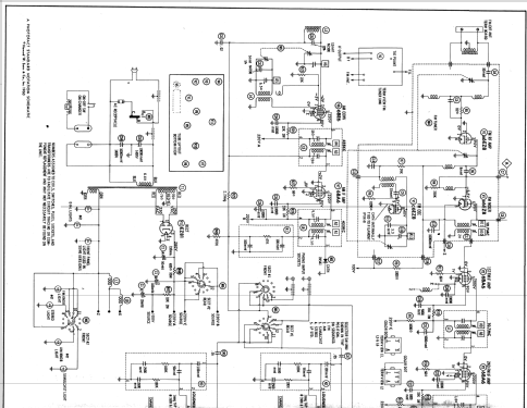
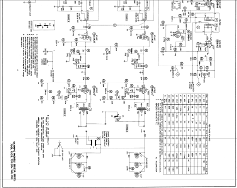
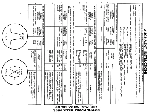
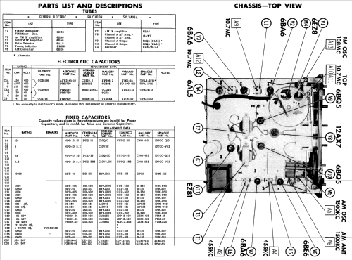
Click on the schematic thumbnail to request the schematic as a free document.
- Number of Tubes
- 11
- Main principle
- Superheterodyne (common)
- Wave bands
- Broadcast (BC) and FM or UHF.
- Details
- Changer (Record changer)
- Power type and voltage
- Alternating Current supply (AC) / 110 - 120 Volt
- Loudspeaker
- 6 Loudspeakers
- from Radiomuseum.org
- Model: 7501 Ch= 150 - Olympic Radio & Television,
- Notes
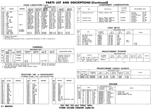
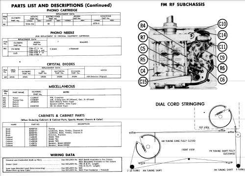
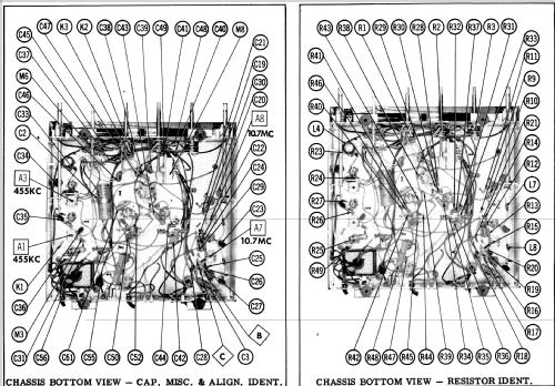
- AC operated AM - FM receiver with stereo output and 4 speed automatic record changer. Sams photofact set 501 folder 12 date 10-60 features the Olympic models 7501, 7502 and 7511 as the same schematic.
- Literature/Schematics (1)
- Photofact Folder, Howard W. SAMS (Set 501 folder 12 date 10-60)
- Author
- Model page created by Peter Hoddow. See "Data change" for further contributors.
- Other Models
-
Here you find 608 models, 273 with images and 556 with schematics for wireless sets etc. In French: TSF for Télégraphie sans fil.
All listed radios etc. from Olympic Radio & Television, Inc.; New York (NY)
Forum contributions about this model: Olympic Radio &: 7501 Ch= 150
Threads: 1 | Posts: 1
OLYMPIC MODELS 7501 problem neighborhoods:
On ebay Amoy to the tube of an American movement OLYMPIC MODELS 7501, carefully checked after the arrival of the radio, because it is the product of the United States the power supply is 110v, mainland China is 220v to find a power transformer plug in the antenna, power on: Question: hum, but no station.
I the website Radiaomuseum.org I like to download the 7501 circuit diagram, calibrated in accordance with the drawings, careful examination of the entire circuit voltage: power filter voltage is not allowed, I replaced the filter with electrolytic capacitors: 100UF A , 50UF a, 10uf. Power on, normal listening.
Problems Neighborhoods:
High voltage power transformer, line icon set is 250v, and I measured 280v
By EZ81 rectified voltage line (feet) icon set is 280v, my 320v;
The calibration through three filter capacitor voltage drawings is 220v, and I measured 245v;
Entire power measurements to be much higher than the drawings 20-30v, Neighborhoods: Does this can be? Whether it will be a problem? How the voltage down?
Is there any way? Thank you teachers.
Thank you: Radiomuseum.org
Here, I find I need the drawings;
Tube radios OLYMPIC MODELS 7501
Here, I am learning to repair tube radios of knowledge;
I am here to solve a lot of difficulties, help me progress.
Thanks again.
Yuxi WANG, 11.Mar.13
