Ultradyne L2 UV tubes
Phenix Radio Corp.; New York
- Pays
- Etats-Unis
- Fabricant / Marque
- Phenix Radio Corp.; New York
- Année
- 1924/1925
- Catégorie
- Radio - ou tuner d'après la guerre 1939-45
- Radiomuseum.org ID
- 50438
-
- alternative name: Lacault, R.E.


Radio News, Feb.1925, p.1463

Radio Broadcast, Nov. 1924, p. 111

Radio Broadcast, Nov. 1924, p. 303

Radio Broadcast, Mar. 1925, p. 943

Radio Broadcast, Apr. 1925, p. 1129


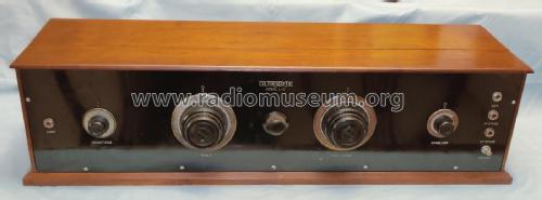
RLE Phenix Ultradyne L2 Kit.
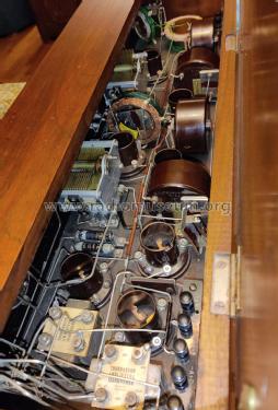
From the right end
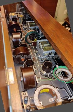
From the left end
Cliquez sur la vignette du schéma pour le demander en tant que document gratuit.
- No. de tubes
- 8
- Principe général
- Super hétérodyne (en général); FI/IF 115 kHz
- Circuits accordés
- 7 Circuits MA (AM)
- Gammes d'ondes
- PO uniquement
- Tension / type courant
- Piles (rechargeables ou/et sèches)
- Haut-parleur
- - Ce modèle nécessite des HP externes
- Matière
- Boitier en bois
- De Radiomuseum.org
- Modèle: Ultradyne L2 [UV tubes] - Phenix Radio Corp.; New York
- Forme
- Modèle de table boitier avec vouvercle
- Dimensions (LHP)
- 32 x 9 x 10 inch / 813 x 229 x 254 mm
- Remarques
- The Ultradyne L2 was first manufactured for the UV201A with thoriated filament, which was announced in December 1922. In August 1925 the UV201A was withdrawn and replaced by the UX201A. They have later also been fitted with UX112, UX171 or UX171A but we don't put that into the tube line up as "or" because that was at least a year later of the UX201A variant.
The Ultradyne L2 is a super with RF reaction. Whether it is similar to the Keystone L2's is uncertain. The manufacturer Keystone Radio Service offered kits according to The Radio Trade Directory of Aug.,1925.
Two dials (primary tuning control knobs).
Siehe auch Triodensuperhets.
- Source extérieure
- Ernst Erb
- Source du schéma
- Rider's Perpetual, Volume 1 = 1931/1934 (for 1919-1931)
- Schémathèque (1)
- Rider's Perpetual, Volume 1 = 1931/1934 (1919 to 1931) (see misc. 1-11 Lacault)
- Schémathèque (2)
- Radio Broadcast, Nov. 1924, p. 111
- D'autres Modèles
-
Vous pourrez trouver sous ce lien 15 modèles d'appareils, 9 avec des images et 5 avec des schémas.
Tous les appareils de Phenix Radio Corp.; New York
Collections
Le modèle Ultradyne fait partie des collections des membres suivants.
Contributions du forum pour ce modèle: Phenix Radio Corp.;: Ultradyne L2
Discussions: 1 | Publications: 1
Die Besonderheit der Ultradyne-Schaltung liegt darin, dass die Mischtriode keine Anodengleichspannung erhält. Stattdessen liegt sie an der Oszillatorwechselspannung. und wird damit voll durchgesteuert.
Die Anodenspannung für die Mischtriode kommt galvanisch über mehrere Spulen (1.ZF-Filter und Eingangskreis-Rückkopplung) vom Gitter der Oszillatorröhre. Am Gitter der Oszillatorröhre steht die Schwingung leicht ins negative verschoben, mit 50 V positiver und 60 V negativer Halbwelle. Entsprechend an der Mischeranode (Oszillogramm ohne Eingangssignal, bei verstimmtem Eingangskreis).
20V/div. 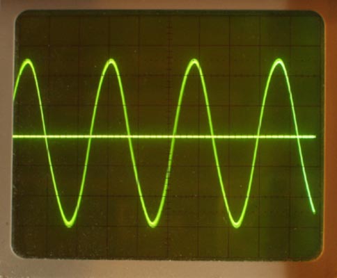
Konrad Birkner † 12.08.2014, 02.Sep.11