- Country
- United States of America (USA)
- Manufacturer / Brand
- Philco, Philadelphia Stg. Batt. Co.; USA
- Year
- 1933
- Category
- Broadcast Receiver - or past WW2 Tuner
- Radiomuseum.org ID
- 139385
Click on the schematic thumbnail to request the schematic as a free document.
- Number of Tubes
- 6
- Main principle
- Superhet with RF-stage; ZF/IF 260 kHz
- Wave bands
- Broadcast (MW), Police, sometimes also early TV (75-200m).
- Power type and voltage
- Alternating Current supply (AC) / 115 Volt
- Loudspeaker
- Electro Magnetic Dynamic LS (moving-coil with field excitation coil)
- Material
- Wooden case
- from Radiomuseum.org
- Model: 19L - Philco, Philadelphia Stg. Batt
- Shape
- Console, Lowboy (legs < 50 %).
- Notes
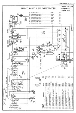
- The individual models for the 19 series include: 19B cathedral (early and late), 19LZ chairside (early and late), 19LZX chairside with separate large speaker cabinet (early and late), 19H highboy, 19L lowboy, 19TX compact table radio with separate large speaker cabinet, and three versions of 19X console with different cabinet styles -- an early version with 4 pillars and an arched control panel, a middle version with no pillars and a square control panel, and a late version with three narrow pillars in the center of the speaker grill and figures of musicians around the dial escutcheon. The model 19 series chassis is similar to model 89, except that model 19 has a shadow meter (tuning aid). The model 19 chassis evolved through a number of chassis codes from 121 through 128. Two Philco schematic diagrams (also included in Rider vols 3 and 4) are available, an earlier version (no code shown, but consistent with early runs of code 121) for models 19 and 89, with single band coverage, a two position tone control, and the power switch coupled to the volume control. Models with this design have 3 knobs, and include the early versions of models 19B, 19LZ, and 19LZX. The second Philco schematic is for model 19 code 128, with dual band coverage, a four position tone control, and combined power / band switch. Models using designs similar to this have four knobs, and include 19B (late), 19LZ (late), 19LZX (late), 19H, 19L, 19TX, and all three versions of 19X. It is not yet clear exactly which chassis codes and run numbers include the later features; however it is known that later runs of code 121, as well as codes 122, 126, and 128 have two bands and four knobs, and therefore are "later" versions. Although the code 128 schematic found in "Philco Wiring Diagrams... 1928-1936" shows an IF frequency of 460 kHz, another page in the same source, as well additional citings in Rider, show 260 kHz for all versions of model 19.
- Circuit diagram reference
- Rider's Perpetual, Volume 3 = 1933 and before
- Mentioned in
- Philco Radio 1928-1942
- Literature/Schematics (1)
- Rider's Perpetual, Volume 4 = ca. 1934 and before (Philco 1928-36 Wiring Diagrams, Parts Lists, and Essential Service Data)
- Author
- Model page created by Thomas Albrecht. See "Data change" for further contributors.
- Other Models
-
Here you find 4120 models, 2227 with images and 3768 with schematics for wireless sets etc. In French: TSF for Télégraphie sans fil.
All listed radios etc. from Philco, Philadelphia Stg. Batt. Co.; USA


