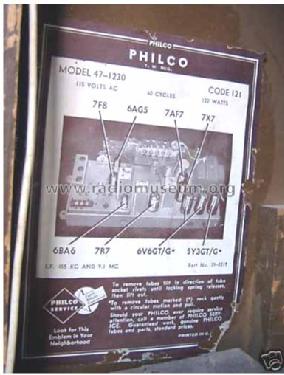
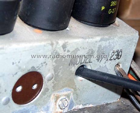
47-1230FM Radio-Phonograph
Philco, Philadelphia Stg. Batt. Co.; USA
- Produttore / Marca
- Philco, Philadelphia Stg. Batt. Co.; USA
- Anno
- 1946/1947
- Categoria
- Radio (o sintonizzatore del dopoguerra WW2)
- Radiomuseum.org ID
- 50879
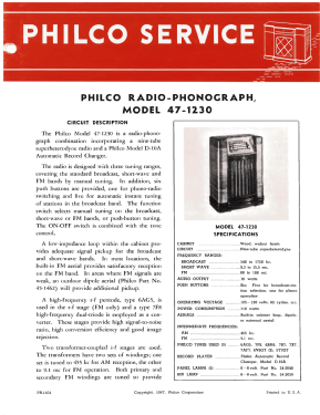

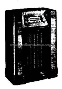
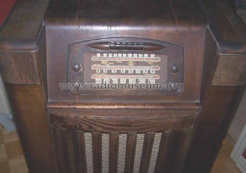
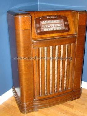
Philco 47-1230 seen from the front
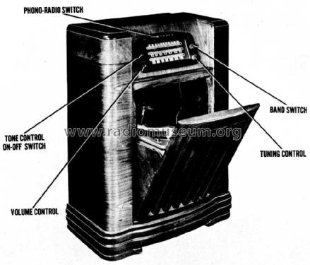
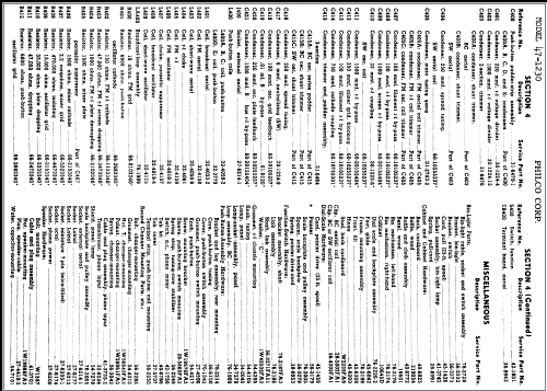
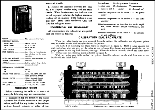
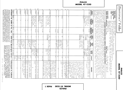
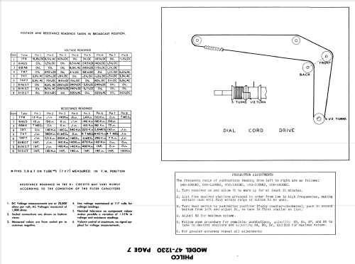
SAMS Photofact
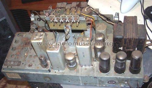
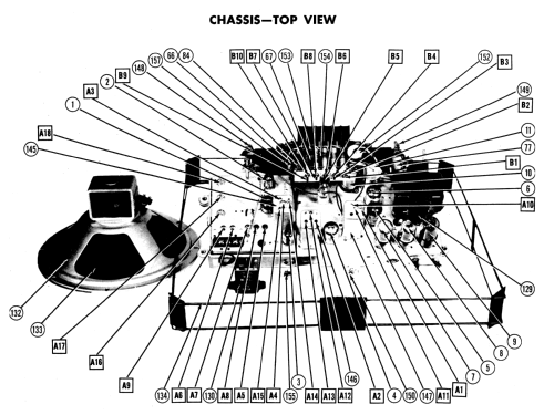
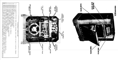
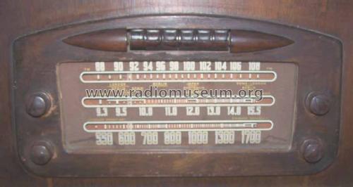
Philco 47-1230 front-top section
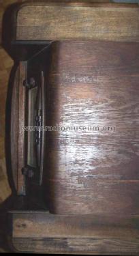
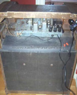
Top of the cabinet of a 47-1230
Clicca sulla miniatura dello schema per richiederlo come documento gratuito.
- Numero di tubi
- 9
- Principio generale
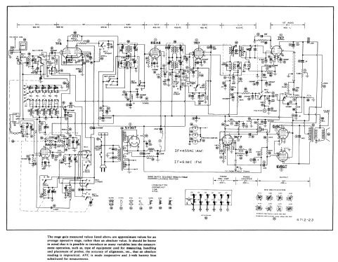
- Supereterodina (in generale); ZF/IF 455/9100 kHz
- N. di circuiti accordati
- 8 Circuiti Mod. Amp. (AM) 9 Circuiti Mod. Freq. (FM)
- Gamme d'onda
- Onde medie (OM), corte (OC) e FM.
- Particolarità
- Giradischi o cambiadischi
- Tensioni di funzionamento
- Alimentazione a corrente alternata (CA) / 105-120 Volt
- Altoparlante
- AP elettrodinamico (bobina mobile e bobina di eccitazione/di campo) / Ø 12 inch = 30.5 cm
- Potenza d'uscita
- 10 W (qualità ignota)
- Materiali
- Mobile in legno
- Radiomuseum.org
- Modello: 47-1230FM Radio-Phonograph - Philco, Philadelphia Stg. Batt
- Forma
- Console con tastiera/pulsantiera.
- Dimensioni (LxAxP)
- 28 x 38 x 14.25 inch / 711 x 965 x 362 mm
- Annotazioni
- The "Chicago Daily Tribune" August 17, 1947 contains an ad from Philco for the following models: 1226, 1230FM, 1227FM, 1201, 360 and 1256. It is a typical add for selling out the 1226, 1230FM and 1227FM with a trade in of 30 $. This model is advertised as 1230FM with a price of $ 269.50 less trade-in. Later Philco will offer the "1948 line" in fact 1947/48. This model uses model D-10A Automatic Record Changer.
- Fonte esterna dei dati
- Ernst Erb
- Fonte dei dati
- Collector's Guide to Antique Radios 4. Edition
- Riferimenti schemi
- Rider's Perpetual, Volume 19 = 1949 and before
- Letteratura / Schemi (1)
- Philco Home Radio Yearbook 1946-1947
- Letteratura / Schemi (2)
- - - Manufacturers Literature (Philco Service Manual - Philco Radio-Phonograph Model 47-1230)
- Altri modelli
-
In questo link sono elencati 4120 modelli, di cui 2227 con immagini e 3768 con schemi.
Elenco delle radio e altri apparecchi della Philco, Philadelphia Stg. Batt. Co.; USA
Collezioni
Il modello 47-1230FM fa parte delle collezioni dei seguenti membri.
Discussioni nel forum su questo modello: Philco, Philadelphia: 47-1230FM Radio-Phonograph
Argomenti: 1 | Articoli: 2
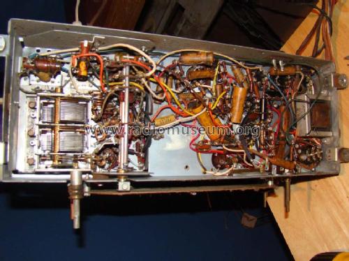
Greetings.
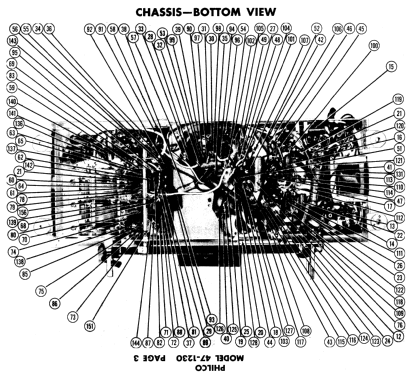
While restoring my own Philco 47-1230, I noticed that the original Philco Service Manual had errors in its part placement drawing, meant to help locating probing location for diagnostic. I was relying on this for capacitor replacement and have bad surprises...
Riders volume 19 used an exact copy of the service manuals.
I heard there are many errors in the vintage documents, to prevent problems, nothing like pointing them out.
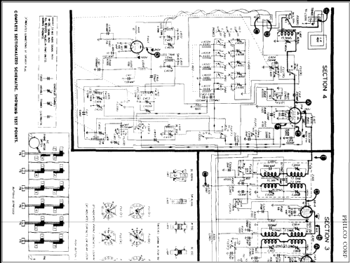
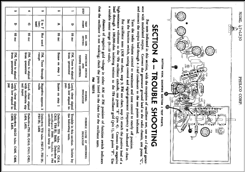
Here's C419 how it is (erroneously) drawn in the diagnostic pages for section 4:


 The pins at wich the C419 are connected are wrong. They aren't what I saw in my 47-1230, and they aren't what I see in the diagrams. The C419 is connected from GND to R410 (and C102a), the 4th pin from the bottom of the lug strip, not L404, 3rd pin from the top of the lug strip. Note that the 3rd top and 3rd bottom are bolted to the chassis (GND) so if it were like in the drawing, the capacitor would be between two GNDs.
here's how I think it should be drawn
Allegati
- Error in the parts placement diagram of 47-1230 service manual (52 KB)
- original 47-1230 schematics (25 KB)
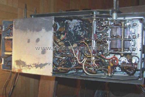
- Inside the chassis of my 47-1230 prior to alterations (188 KB)
- C419 in my 47-1230 with comments (190 KB)
- How I believe it should be written. (52 KB)
- thumbnail for error image (6 KB)
- thumbnail for schematics (7 KB)
- thumbnail for my 47-1230 (no comments) (14 KB)
- thumbnail for my 47-1230 (comments) (14 KB)
- thumbnail for my correction (6 KB)
Yan Lauzon, 11.Jul.11