90 Baby Grand Middle
Philco, Philadelphia Stg. Batt. Co.; USA
- Land
- USA
- Hersteller / Marke
- Philco, Philadelphia Stg. Batt. Co.; USA
- Jahr
- 1931

- Kategorie
- Rundfunkempfänger (Radio - oder Tuner nach WW2)
- Radiomuseum.org ID
- 18816


By courtesy of Kevin Roberts, Atkins, USA.
Scanned from the Philco Folder 2674.
Scanned from the Philco Folder 2674.

From a Portuguese auction.
Klicken Sie auf den Schaltplanausschnitt, um diesen kostenlos als Dokument anzufordern.
- Anzahl Röhren
- 9
- Hauptprinzip
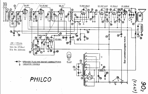
- Super mit HF-Vorstufe; ZF/IF 175 kHz
- Anzahl Kreise
- 7 Kreis(e) AM
- Wellenbereiche
- Mittelwelle, keine anderen.
- Betriebsart / Volt
- Wechselstromspeisung / 50 to 60 cycles, 115 Volt
- Lautsprecher
- Dynamischer LS, mit Erregerspule (elektrodynamisch)
- Material
- Gerät mit Holzgehäuse
- von Radiomuseum.org
- Modell: 90 Baby Grand [Middle] - Philco, Philadelphia Stg. Batt
- Form
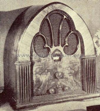
- Tischgerät, Kathedralenform (Hochformat, bogig bis spitzbogig, nicht nur runde Ecken).
- Abmessungen (BHT)
- 0 x 18 x 0 inch / 0 x 457 x 0 mm
- Bemerkung
-
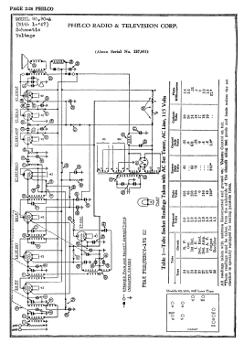
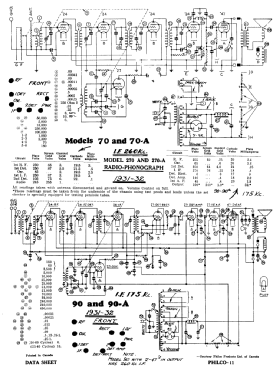
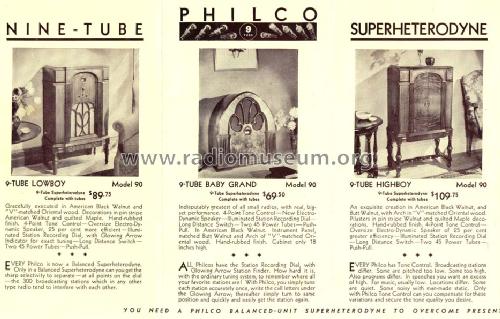
Models 90 and 90A were available in a cathedral, a lowboy, and a highboy cabinet. The chassis was made in three versions - an early model 90 and 90A with two 45 output tubes in push-pull, a middle version with one 47 output tube, and a late version with two 47 output tubes. Model 90 is for 115 VAC 50-60 Hz; model 90A is for 115 VAC 25-60 Hz.
The models 90 and 90A "early" and "middle" have a 4-gang tuning condenser plus 3 tuned IF circuit - both with IF 175 (Rider's change note 8-3). The version "middle", which are above serial number 237,001, of the model 90 and 90A has tubes: 24 RF, 27 osc, 24 1st det., 24 IF, 27 2nd det. rect., 27 det. amp., 27 1st AF amp, 47 output and 80 rectifier. The "late" model 90 and 90A again have push-pull output but with 2 x 47 tubes. See Rider's Philco 3-35 for IF 260 kHz. Applied on models serial B-32001 to B-35000 and above B-53100. They have a 3-gang tuning condenser and only 6 tuned circuits. The same differences can be found for all cabinets, both 90 and 90A: Baby Grand (Cathedral), Lowboy and Highboy (with a stretcher).
The cathedral cabinet is the classic design by Edward L. Coombs, and is similar to the cathedral versions of model 21, 35, 46, and 70. [3331438-1133]
- Originalpreis
- 69.00 $
- Datenherkunft extern
- E. Erb 3-907007-36-0
- Schaltungsnachweis
- Die «Thali Schemasammlung» führt das Modell.
- Literaturnachweis
- Philco Radio 1928-1942
- Literatur/Schema (1)
- Rider's Perpetual, Volume 2 = 1932 and before (Philco 1928-36 Wiring Diagrams, Parts Lists, and Essential Service Data)
- Literatur/Schema (3)
- Philco Folder 2674.
- Weitere Modelle
-
Hier finden Sie 4126 Modelle, davon 2231 mit Bildern und 3774 mit Schaltbildern.
Alle gelisteten Radios usw. von Philco, Philadelphia Stg. Batt. Co.; USA
Forumsbeiträge zum Modell: Philco, Philadelphia: 90 Baby Grand
Threads: 2 | Posts: 8
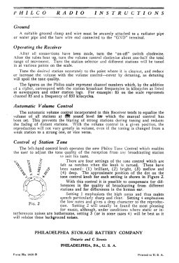
What does the open circle and filled in square mean on a scematic? See attached
The radio I'm working on (Philco Model 90 Middle) has two capacitors on each leg of the incoming AC power going to ground. Are they necessary? It seems to me to be an accident waiting to happen. See attached
Anlagen
- Schematic (44 KB)
- Schematic 2 (12 KB)
James Hochstetler, 05.Jan.22
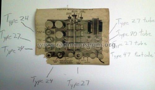
First of all I'm a beginner to radio restoration. My question is on the capacitors packed inside the two metal containers 24 and 30. 24 says it has 4 capacitors inside but only has 3 leads exiting the container. 30 say it has two capacitors inside but has 3 leads exiting the container. On the schematic it shows 24, 4 (four) times but no values listed. 30 shows up twice but again no value. The values are different on all 6 capacitors so how do I know which one goes where? Am I missing something? One more question on polarity of the two electrolytics, 56 and 57. The schematic does not indicate polarity. My intuition says + for 56 goes to the choke 55. On 57, negative generally goes to ground. Any thoughts or help would be appreciated.
P.S. Am I the only one that doesn't like codes inside a circle rather than the actual value?
James Hochstetler, 01.Dec.21