90A Highboy Middle
Philco, Philadelphia Stg. Batt. Co.; USA
- Country
- United States of America (USA)
- Manufacturer / Brand
- Philco, Philadelphia Stg. Batt. Co.; USA
- Year
- 1931

- Category
- Broadcast Receiver - or past WW2 Tuner
- Radiomuseum.org ID
- 138522
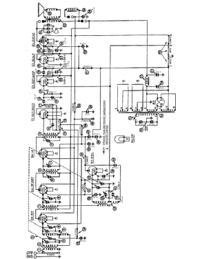
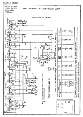
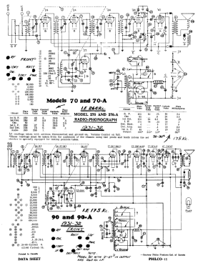
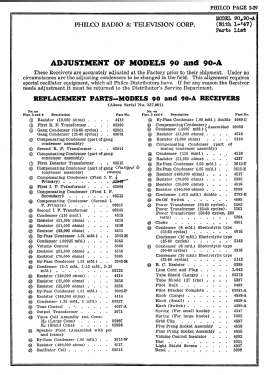
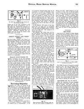
Click on the schematic thumbnail to request the schematic as a free document.
- Number of Tubes
- 9
- Main principle
- Superhet with RF-stage; ZF/IF 175 kHz
- Tuned circuits
- 7 AM circuit(s)
- Wave bands
- Broadcast only (MW).
- Power type and voltage
- Alternating Current supply (AC) / 25 to 60 cycles, 115 Volt
- Loudspeaker
- Electro Magnetic Dynamic LS (moving-coil with field excitation coil)
- Material
- Wooden case
- from Radiomuseum.org
- Model: 90A Highboy [Middle] - Philco, Philadelphia Stg. Batt
- Shape
- Console, Highboy (legs > 50 %).
- Notes
-
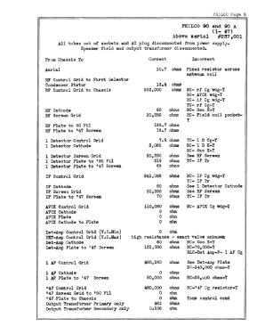
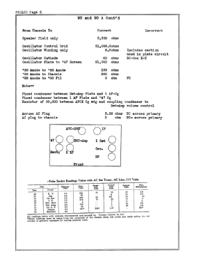
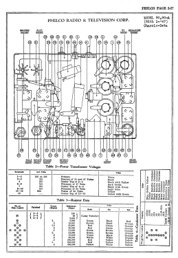
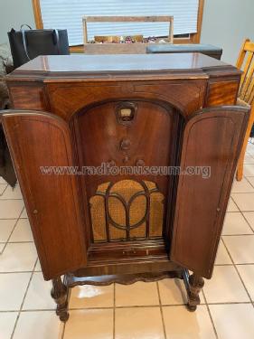
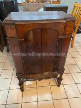
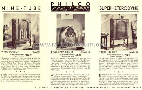
Models 90 and 90A were available in a cathedral, a lowboy, and a highboy cabinet. The chassis was made in three versions - an early model 90 and 90A with two 45 output tubes in push-pull, a middle version with one 47 output tube, and a late version with two 47 output tubes. Model 90 is for 115 VAC 50-60 Hz; model 90A is for 115 VAC 25-60 Hz.
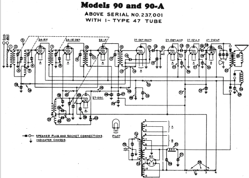
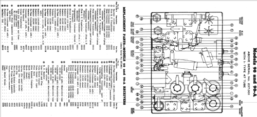
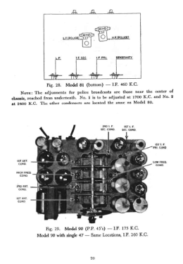
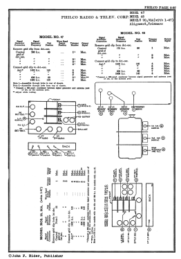
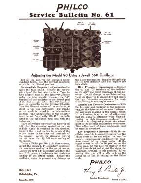
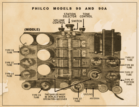
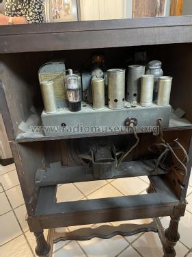
The models 90 and 90A "early" and "middle" have a 4-gang tuning condenser plus 3 tuned IF circuit - both with IF 175 (Rider's change note 8-3). The version "middle", which are above serial number 237,001, of the model 90 and 90A has tubes: 24 RF, 27 osc, 24 1st det., 24 IF, 27 2nd det. rect., 27 det. amp., 27 1st AF amp, 47 output and 80 rectifier. The "late" model 90 and 90A again have push-pull output but with 2 x 47 tubes. See Rider's Philco 3-35 for IF 260 kHz. Applied on models serial B-32001 to B-35000 and above B-53100. They have a 3-gang tuning condenser and only 6 tuned circuits. The same differences can be found for all cabinets, both 90 and 90A: Baby Grand (Cathedral), Lowboy and Highboy (with a stretcher).
The cathedral cabinet is the classic design by Edward L. Coombs, and is similar to the cathedral versions of model 21, 35, 46, and 70.
- Price in first year of sale
- 109.00 $
- Source of data
- Philco Radio 1928-1942
- Circuit diagram reference
- Rider's Perpetual, Volume 2 = 1932 (Models 1931/1932)
- Literature/Schematics (1)
- Philco 1928-36 Wiring Diagrams, Parts Lists, and Essential Service Data
- Literature/Schematics (3)
- Philco Folder 2674.
- Author
- Model page created by Thomas Albrecht. See "Data change" for further contributors.
- Other Models
-
Here you find 4086 models, 2222 with images and 3734 with schematics for wireless sets etc. In French: TSF for Télégraphie sans fil.
All listed radios etc. from Philco, Philadelphia Stg. Batt. Co.; USA
