- Pays
- Australie
- Fabricant / Marque
- Philco Radio & Television Corp. (Aust) Pty. Ltd.
- Année
- 1937
- Catégorie
- Radio - ou tuner d'après la guerre 1939-45
- Radiomuseum.org ID
- 170765
Cliquez sur la vignette du schéma pour le demander en tant que document gratuit.
- No. de tubes
- 5
- Principe général
- Super hétérodyne (en général); FI/IF 462.5 kHz; 2 Etage(s) BF
- Circuits accordés
- 6 Circuits MA (AM)
- Gammes d'ondes
- PO uniquement
- Tension / type courant
- Alimentation Courant Alternatif (CA) / 240 Volt
- Haut-parleur
- HP dynamique à électro-aimant (électrodynamique) / Ø 8 inch = 20.3 cm
- Matière
- Boitier en bois
- De Radiomuseum.org
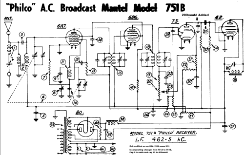
- Modèle: 751B - Philco Radio & Television Corp
- Forme
- Modèle de table vertical (pas forme catédrale)
- Remarques
-
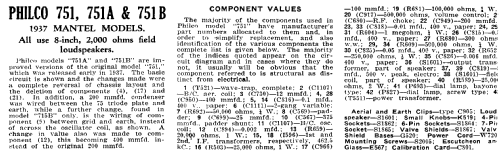
Philco models 751A & 751B are improved versions of the 751 which was released in early 1937.
The basic circuit is as the 751 & the changes made were a complete reversal of chassis layout and the deletion of components 4, 17 & 21. A 200 pF capacitor was wired between the 75 triode plate & earth, while further change, found in 751B only, is the wiring of component 9 between grid & earth, instead of across the oscillator coil, as shown. A change in value also was made to component 12 to 400pF.
- Schémathèque (1)
- Radio Trade Annual 1939 P274.
- Auteur
- Modèle crée par Stuart Irwin. Voir les propositions de modification pour les contributeurs supplémentaires.
- D'autres Modèles
-
Vous pourrez trouver sous ce lien 138 modèles d'appareils, 36 avec des images et 76 avec des schémas.
Tous les appareils de Philco Radio & Television Corp. (Aust) Pty. Ltd.