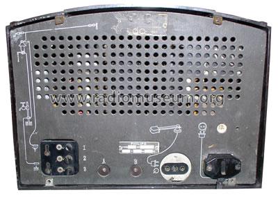
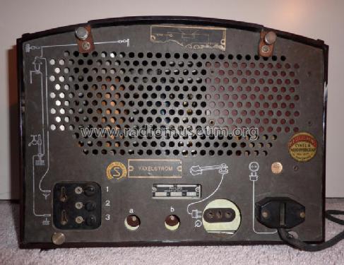
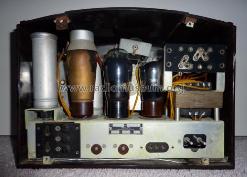
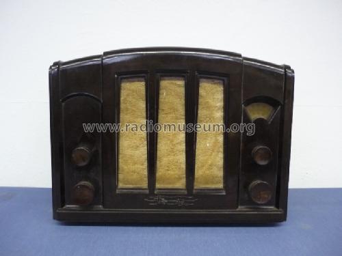
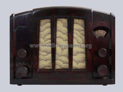
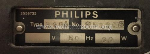
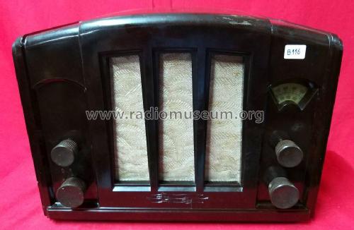
940A 3 Antennenschalter
Philips; Eindhoven (tubes international!); Miniwatt
- Pays
- Pays-Bas
- Fabricant / Marque
- Philips; Eindhoven (tubes international!); Miniwatt
- Année
- 1935
- Catégorie
- Radio - ou tuner d'après la guerre 1939-45
- Radiomuseum.org ID
- 157093
Cliquez sur la vignette du schéma pour le demander en tant que document gratuit.
- No. de tubes
- 3
- Principe général
- Récepteur TRF - par réaction (régénératif)
- Gammes d'ondes
- PO et GO
- Tension / type courant
- Alimentation Courant Alternatif (CA) / 110-240 Volt
- Haut-parleur
- HP dynamique à aimant permanent + bobine mobile
- Matière
- Boitier en bakélite
- De Radiomuseum.org
- Modèle: 940A [3 Antennenschalter] - Philips; Eindhoven tubes
- Forme
- Modèle de table sans poussoirs, modèle cheminée
- Dimensions (LHP)
- 315 x 245 x 175 mm / 12.4 x 9.6 x 6.9 inch
- Remarques
-
Siehe auch: Philips 940A mit 1 Antennenschalter.
- Poids net
- 7 kg / 15 lb 6.7 oz (15.419 lb)
- Auteur
- Modèle crée par Wolfgang Bauer. Voir les propositions de modification pour les contributeurs supplémentaires.
- D'autres Modèles
-
Vous pourrez trouver sous ce lien 5273 modèles d'appareils, 4419 avec des images et 3458 avec des schémas.
Tous les appareils de Philips; Eindhoven (tubes international!); Miniwatt
Collections
Le modèle fait partie des collections des membres suivants.
Contributions du forum pour ce modèle: Philips; Eindhoven: 940A
Discussions: 1 | Publications: 2
Gentlemen
Two weeks ago I found a beautiful specimen of this model on a flea market. Not only was it all original but also it had the sales rep label intact showing that it was originally sold here in my home town.
I have never met any antique radio in such a great condition so I took it on my shop desk even if I have some other radios "under maintenance".
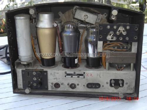
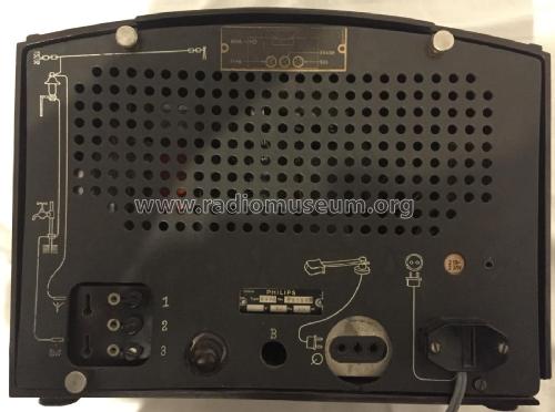
There are several versions of schematics on Radiomuseum site, but none of them depict accurately the front end circuits. This model has three switching screws and the front end design is reminiscent of the czech model 944A series Z. It clearly has two wave traps for the two bands but also the MW wave trap has a wide range since the coil has two switchable winding sections.
I have drafted an accurate schematic of this model, which I believe has been standard for at least the Finnish market.
I would also be interested to hear how the three switch screws have originaly been used. Apart from acting as a switch they clearly allow some external wires to be connected.
Harri Lumme
Pièces jointes
- 940A_variant (59 KB)
Harri Lumme, 16.Oct.22


