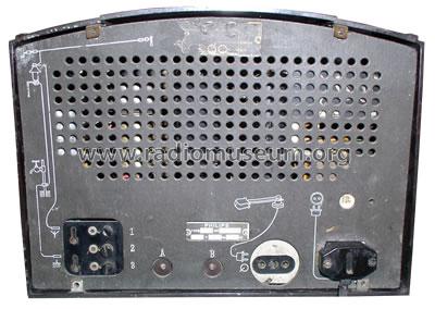
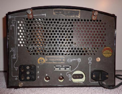
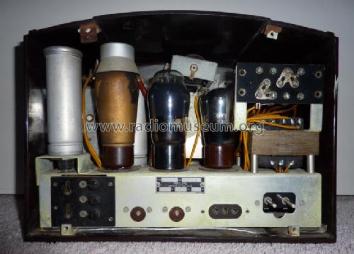
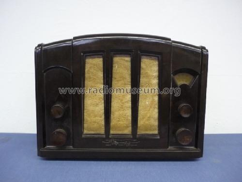
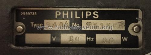
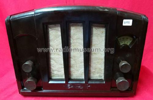
940A 3 Antennenschalter
Philips; Eindhoven (tubes international!); Miniwatt
- Land
- Niederlande
- Hersteller / Marke
- Philips; Eindhoven (tubes international!); Miniwatt
- Jahr
- 1935
- Kategorie
- Rundfunkempfänger (Radio - oder Tuner nach WW2)
- Radiomuseum.org ID
- 157093
Klicken Sie auf den Schaltplanausschnitt, um diesen kostenlos als Dokument anzufordern.
- Anzahl Röhren
- 3
- Hauptprinzip
- Geradeaus oder Audion mit Rückkopplung
- Wellenbereiche
- Langwelle, Mittelwelle (LW+MW).
- Betriebsart / Volt
- Wechselstromspeisung / 110-240 Volt
- Lautsprecher
- Dynamischer LS, keine Erregerspule (permanentdynamisch)
- Material
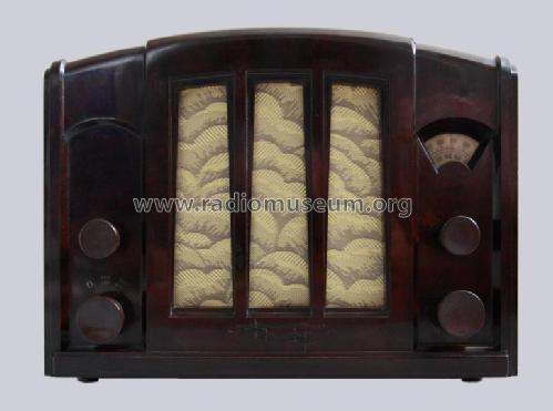
- Bakelit (Pressstoff)
- von Radiomuseum.org
- Modell: 940A [3 Antennenschalter] - Philips; Eindhoven tubes
- Form
- Tischgerät ohne Drucktasten, bis 35 cm Breite (Kleingerät, meist dekorativ. Nur für Netzbetrieb, doch Transportgriff möglich).
- Abmessungen (BHT)
- 315 x 245 x 175 mm / 12.4 x 9.6 x 6.9 inch
- Bemerkung
-
Siehe auch: Philips 940A mit 1 Antennenschalter.
- Nettogewicht
- 7 kg / 15 lb 6.7 oz (15.419 lb)
- Autor
- Modellseite von Wolfgang Bauer angelegt. Siehe bei "Änderungsvorschlag" für weitere Mitarbeit.
- Weitere Modelle
-
Hier finden Sie 5280 Modelle, davon 4428 mit Bildern und 3461 mit Schaltbildern.
Alle gelisteten Radios usw. von Philips; Eindhoven (tubes international!); Miniwatt
Sammlungen
Das Modell befindet sich in den Sammlungen folgender Mitglieder.
Forumsbeiträge zum Modell: Philips; Eindhoven: 940A
Threads: 1 | Posts: 2
Gentlemen
Two weeks ago I found a beautiful specimen of this model on a flea market. Not only was it all original but also it had the sales rep label intact showing that it was originally sold here in my home town.
I have never met any antique radio in such a great condition so I took it on my shop desk even if I have some other radios "under maintenance".
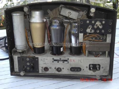
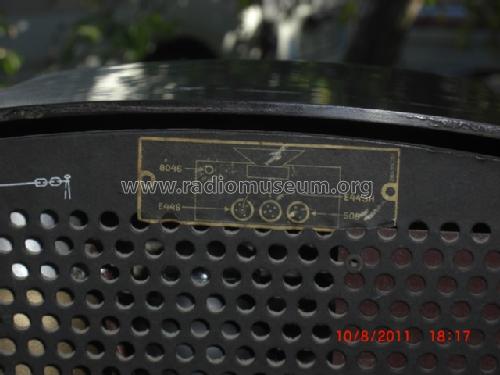
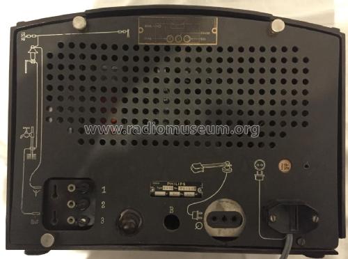
There are several versions of schematics on Radiomuseum site, but none of them depict accurately the front end circuits. This model has three switching screws and the front end design is reminiscent of the czech model 944A series Z. It clearly has two wave traps for the two bands but also the MW wave trap has a wide range since the coil has two switchable winding sections.
I have drafted an accurate schematic of this model, which I believe has been standard for at least the Finnish market.
I would also be interested to hear how the three switch screws have originaly been used. Apart from acting as a switch they clearly allow some external wires to be connected.
Harri Lumme
Anlagen
- 940A_variant (59 KB)
Harri Lumme, 16.Oct.22


