B5X42A /01 /02
Philips; Eindhoven (tubes international!); Miniwatt
- Country
- Netherlands
- Manufacturer / Brand
- Philips; Eindhoven (tubes international!); Miniwatt
- Year
- 1964/1965
- Category
- Broadcast Receiver - or past WW2 Tuner
- Radiomuseum.org ID
- 29733


aus ebay, mit Erlaubnis des Verkäufers em85

aus ebay, mit Erlaubnis des Verkäufers em85

aus ebay, mit Erlaubnis des Verkäufers em85

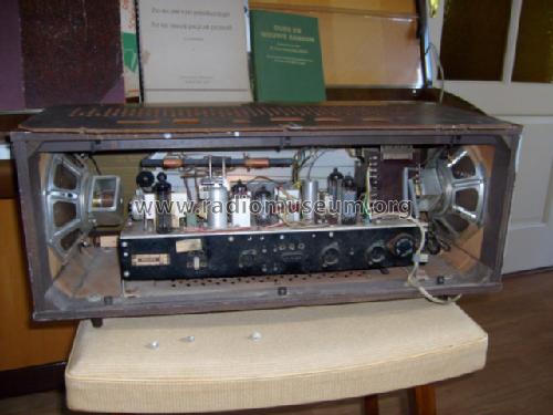


Foto de Francisco Martins
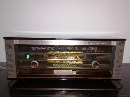
Foto de Francisco Martins
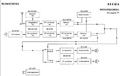
Click on the schematic thumbnail to request the schematic as a free document.
- Number of Tubes
- 10
- Main principle
- Superheterodyne (common); ZF/IF 452/10700 kHz
- Tuned circuits
- 6 AM circuit(s) 11 FM circuit(s)
- Wave bands
- Broadcast, Long Wave, Short Wave plus FM or UHF.
- Power type and voltage
- Alternating Current supply (AC) / 110-245 Volt
- Loudspeaker
- 2 Loudspeakers
- Power out
- 4 W (unknown quality)
- Material
- Wooden case
- from Radiomuseum.org
- Model: B5X42A /01 /02 - Philips; Eindhoven tubes
- Shape
- Tablemodel with Push Buttons.
- Dimensions (WHD)
- 620 x 240 x 240 mm / 24.4 x 9.4 x 9.4 inch
- Notes
-
Lautsprecher 800 Ohm über Trafo; keine eisenlose Endstufe!
Ausführung:
- /00 helles Gehäuse
- /01 dunkles Gehäuse
- Net weight (2.2 lb = 1 kg)
- 10.5 kg / 23 lb 2 oz (23.128 lb)
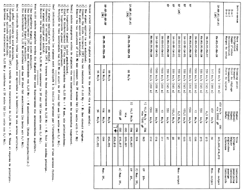
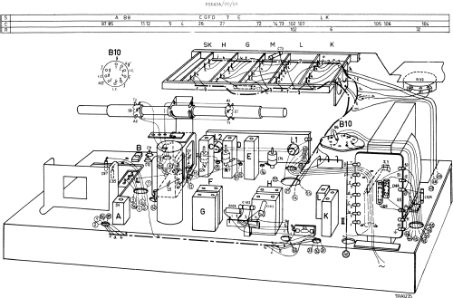
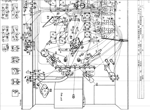
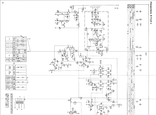
- Literature/Schematics (1)
- -- Original-techn. papers.
- Author
- Model page created by Iven Müller. See "Data change" for further contributors.
- Other Models
-
Here you find 5270 models, 4414 with images and 3457 with schematics for wireless sets etc. In French: TSF for Télégraphie sans fil.
All listed radios etc. from Philips; Eindhoven (tubes international!); Miniwatt
Collections
The model is part of the collections of the following members.
Forum contributions about this model: Philips; Eindhoven: B5X42A /01 /02
Threads: 2 | Posts: 6
I'm the owner of a Philips B5X42A that I've just opened and started to renovate. To my surprise I found a capacitor connected to two lugs (lug 3 and 4) near the back of the radio that was shorted by purpose with a wire. When I then checked to schematics it also showed the same thing.The capacitor is C107 in the schematic (10nF). The short circuit over this capacitor also makes a short circuit over R101 (10kOhm) and C100 (80uF). Can anyone, with more knowledge, please explain the purpose of this circuit? It sure puzzles me.
Mats Oscarsson, 01.Jun.17
I am about to restore a somewhat neglected model but my first obstacle is getting the set out of its case. After removing the screws on the base, I find I cannot slide the chasis out of its case as the two speakers are in the way. Removing the speakers might be the obvious next step but their fixing screws are very inaccessible with the chassis still in place. Before I do this I would be interested to know if anyone has an easier way to get the set out of its box or if I am missing something here??!
Christopher Morrison, 08.Oct.10