B5X42A /01 /02
Philips; Eindhoven (tubes international!); Miniwatt
- Pays
- Pays-Bas
- Fabricant / Marque
- Philips; Eindhoven (tubes international!); Miniwatt
- Année
- 1964/1965
- Catégorie
- Radio - ou tuner d'après la guerre 1939-45
- Radiomuseum.org ID
- 29733
Cliquez sur la vignette du schéma pour le demander en tant que document gratuit.
- No. de tubes
- 10
- Principe général
- Super hétérodyne (en général); FI/IF 452/10700 kHz
- Circuits accordés
- 6 Circuits MA (AM) 11 Circuits MF (FM)
- Gammes d'ondes
- PO, GO, OC et FM
- Tension / type courant
- Alimentation Courant Alternatif (CA) / 110-245 Volt
- Haut-parleur
- 2 HP
- Puissance de sortie
- 4 W (qualité inconnue)
- Matière
- Boitier en bois
- De Radiomuseum.org
- Modèle: B5X42A /01 /02 - Philips; Eindhoven tubes
- Forme
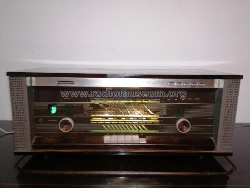
- Modèle de table avec boutons poussoirs.
- Dimensions (LHP)
- 620 x 240 x 240 mm / 24.4 x 9.4 x 9.4 inch
- Remarques
-
Lautsprecher 800 Ohm über Trafo; keine eisenlose Endstufe!
Ausführung:
- /00 helles Gehäuse
- /01 dunkles Gehäuse
- Poids net
- 10.5 kg / 23 lb 2 oz (23.128 lb)
- Schémathèque (1)
- -- Original-techn. papers.
- Auteur
- Modèle crée par Iven Müller. Voir les propositions de modification pour les contributeurs supplémentaires.
- D'autres Modèles
-
Vous pourrez trouver sous ce lien 5279 modèles d'appareils, 4427 avec des images et 3461 avec des schémas.
Tous les appareils de Philips; Eindhoven (tubes international!); Miniwatt
Collections
Le modèle fait partie des collections des membres suivants.
Contributions du forum pour ce modèle: Philips; Eindhoven: B5X42A /01 /02
Discussions: 2 | Publications: 6
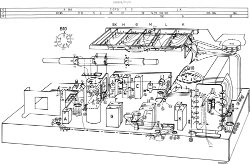
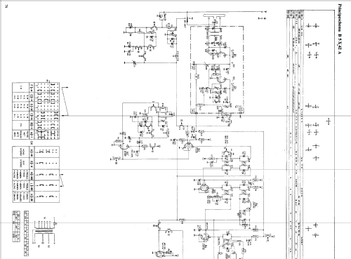
I'm the owner of a Philips B5X42A that I've just opened and started to renovate. To my surprise I found a capacitor connected to two lugs (lug 3 and 4) near the back of the radio that was shorted by purpose with a wire. When I then checked to schematics it also showed the same thing.The capacitor is C107 in the schematic (10nF). The short circuit over this capacitor also makes a short circuit over R101 (10kOhm) and C100 (80uF). Can anyone, with more knowledge, please explain the purpose of this circuit? It sure puzzles me.
Mats Oscarsson, 01.Jun.17
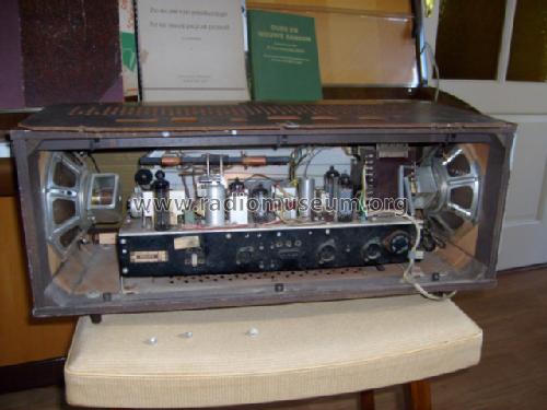
I am about to restore a somewhat neglected model but my first obstacle is getting the set out of its case. After removing the screws on the base, I find I cannot slide the chasis out of its case as the two speakers are in the way. Removing the speakers might be the obvious next step but their fixing screws are very inaccessible with the chassis still in place. Before I do this I would be interested to know if anyone has an easier way to get the set out of its box or if I am missing something here??!
Christopher Morrison, 08.Oct.10


