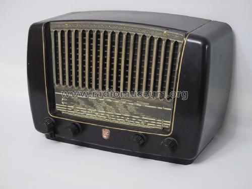
BX310A (BX310A /00)
Philips; Eindhoven (tubes international!); Miniwatt
- País
- Holanda
- Fabricante / Marca
- Philips; Eindhoven (tubes international!); Miniwatt
- Año
- 1951–1953
- Categoría
- Radio - o Sintonizador pasado WW2
- Radiomuseum.org ID
- 29832


Gerät eines Sammlerkollegen

Haga clic en la miniatura esquemática para solicitarlo como documento gratuito.
- Numero de valvulas
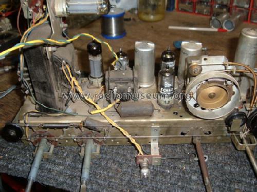
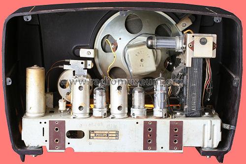
- 5
- Principio principal
- Superheterodino en general; ZF/IF 452 kHz; 2 Etapas de AF
- Número de circuitos sintonía
- 6 Circuíto(s) AM
- Gama de ondas
- OM, OL y OC
- Tensión de funcionamiento
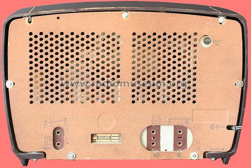
- Red: Corriente alterna (CA, Inglés = AC) / 110; 125; 145; 200; 220; 245 Volt
- Altavoz
- Altavoz dinámico (de imán permanente) / Ø 15 cm = 5.9 inch
- Potencia de salida
- 3 W (unknown quality)
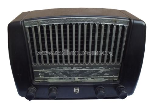
- Material
- Bakelita
- de Radiomuseum.org
- Modelo: BX310A - Philips; Eindhoven tubes
- Forma
- Sobremesa apaisado (tamaño grande).
- Ancho, altura, profundidad
- 380 x 250 x 200 mm / 15 x 9.8 x 7.9 inch
- Anotaciones
-
AM radio for external antenna:
- LW: 152 - 285 kHz.
- BC: 517 - 1622 kHz.
- SW: 5,92 - 18,2 MHz.
Loudspeaker: 9744X (5Ω).Dial lamp: 8045D (E10, 6,3V/320mA).In versions /53 and /90, there are some slight modifications in the parts but not in the general specifications. See the specific version schematics with this model page.
- Peso neto
- 5.9 kg / 12 lb 15.9 oz (12.996 lb)
- Procedencia de los datos
- Technisch- Commercieel - Radio Vademecum Staleman
- Documentación / Esquemas (1)
- -- Original-techn. papers.
- Documentación / Esquemas (2)
- Dépliant Nouvelle Série Philips Radio 1953, Sept. 1952
- Autor
- Modelo creado por Iven Müller. Ver en "Modificar Ficha" los participantes posteriores.
- Otros modelos
-
Donde encontrará 5279 modelos, 4427 con imágenes y 3461 con esquemas.
Ir al listado general de Philips; Eindhoven (tubes international!); Miniwatt
Colecciones
El modelo es parte de las colecciones de los siguientes miembros.
Contribuciones en el Foro acerca de este modelo: Philips; Eindhoven: BX310A
Hilos: 1 | Mensajes: 6
Hello Forum,
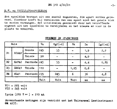
I am restoring a Philips radio type BX310A from 1951/-52. It is generally in quite good shape but has one painful fault; namely internal arcing (= random short circuit) between primary/secondary winding -S23- S24 in the audio output transformer. Trafo's Philips code is A3 152 18.0, and iron core (E+I) size is 40*37*16mm3. Output tube is EL 41 and O/P power 2-3W? The trafo is compact and impregnated with " black tar " so very difficult to open and rewind.
This fault had very interesting symptoms and not so easy to discover. When I smoothly increased AC input voltage by Variac, so around 150V became random "crackle" audible. At the same time one or more arcs happened on tube base socket from anode pin to ground (about 5mm) also a few arcs were visible inside of the tube, especially with higher AC input. These phenomena continued with random rate. Following the anode voltage with oscilloscope showed that the voltage dropped sharply during "crackles". I changed several components and also EL41 + socket at O/P stage without success.
So my final conclusion was a high resistant short circuit between the primary and secondary windings inside of the trafo. One leg of secondary is grounded. Attached drawing shows how I think this phenomenon happens. I also tested the trafo separately with DC voltage and the "crackle " repeated. Normal ohmmeter did not indicate leaking between windings.
Does the arcing happen due to "Spark Coil" effect just like in cars??
Can somebody to advice me are there any means to repair the trafo? Due to trafo construction, rewinding of it look very difficult because of the primary section seems to be top layer. What about availability of adequate replacement trafo (new or surplus)
Best regards
Ake Nyholm
Anexos
- Ph310_audiotrafo-small (149 KB)
- EL41 anodipiiri (18 KB)
Ake Nyholm, 08.Mar.05