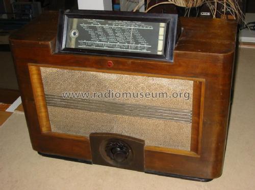
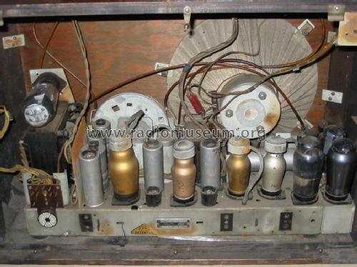
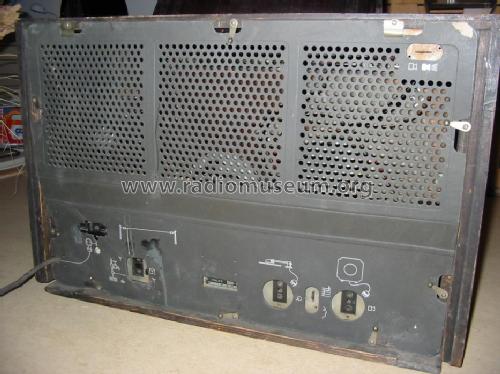
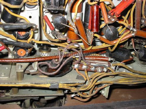
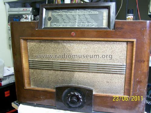
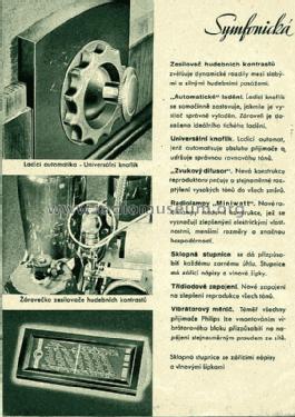
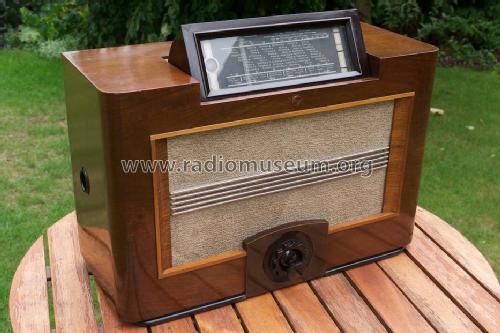
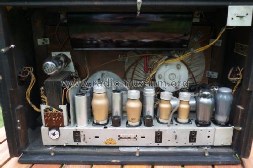
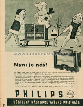
Allegro 890A -14
Philips akc. spol., Praha-Hloubetin
- Country
- Czechoslovakia
- Manufacturer / Brand
- Philips akc. spol., Praha-Hloubetin
- Year
- 1937/1938
- Category
- Broadcast Receiver - or past WW2 Tuner
- Radiomuseum.org ID
- 23182
Click on the schematic thumbnail to request the schematic as a free document.
- Number of Tubes
- 9
- Main principle
- Superheterodyne (common); ZF/IF 128 kHz
- Tuned circuits
- 8 AM circuit(s)
- Wave bands
- Broadcast, Long Wave and Short Wave.
- Power type and voltage
- Alternating Current supply (AC) / 110-245 Volt
- Loudspeaker
- Permanent Magnet Dynamic (PDyn) Loudspeaker (moving coil) / Ø 26 cm = 10.2 inch
- Material
- Wooden case
- from Radiomuseum.org
- Model: Allegro 890A -14 - Philips akc. spol., Praha-
- Shape
- Tablemodel, low profile (big size).
- Dimensions (WHD)
- 610 x 403 x 260 mm / 24 x 15.9 x 10.2 inch
- Notes
-
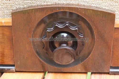
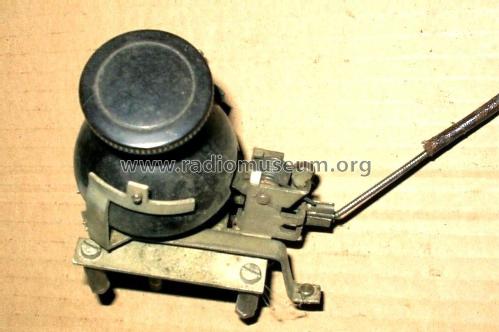
Schaltbare "fühlbare" Abstimmung.
- Price in first year of sale
- 3,000.00 CZK
- External source of data
- Erb
- Source of data
- Ceskoslovenske prijimace 1933-1945, Baudys 1947
- Other Models
-
Here you find 162 models, 137 with images and 124 with schematics for wireless sets etc. In French: TSF for Télégraphie sans fil.
All listed radios etc. from Philips akc. spol., Praha-Hloubetin
Collections
The model Allegro is part of the collections of the following members.
Forum contributions about this model: Philips akc. spol.,: Allegro 890A -14
Threads: 4 | Posts: 10
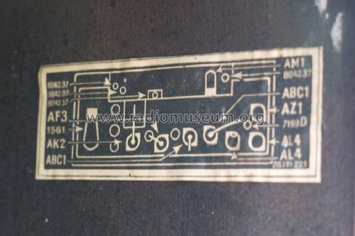
Hello, Friends! I am searching for a usable AM1 magisches auge for my 890A. Usable, so long as it is not too dark. I hope that there is one out there! Please respond via e-mail to:
ac1y[A*T]nc.rr.com
Many thanks!
Sandy Gerli, AC1Y
Alexander Gerli, 19.Jun.11
Hello, friends,
I have acquired an Allegro 890A and am waiting for shipment. I have several questions about this interesting Monoknopf Philips:
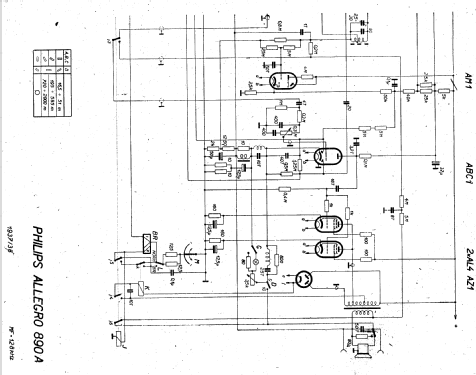
On the schaltbild, there seems to be a rectifier tube (gleichrichter-roehre) at the input side of the audio output transformer. What putpose does this tube serve? I have been around radios a long time, and have been a ham radio operator for 45 years, and I have never seen this arrangement before!
Also, I want to begin gathering a set of spare roehren. Perhaps the most difficult to find will be the AM1 magisches auge. Is there anyone on RMorg who can help me locate one of these in good condition, with usable brightness?
Also, I would like to find several ABC1, AK2 and AF3 and 1561(RGN2004).
If anyone who has this radio can offer me any recommendations as to restoration, I would greatly appreciate it. I have plenty of spare capacitors for the power-supply and interstage bypass requirements.
Many thanks to everyone!
With 73,
Sandy Gerli AC1Y
Alexander Gerli, 03.Jun.11
Frank Blöhbaum, 25.Jan.05
Frank Blöhbaum, 29.Jan.04

