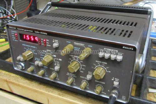
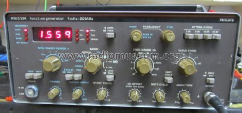
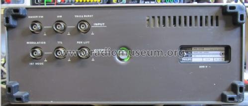
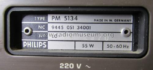
Function Generator 1mHz - 20MHz PM5134
Philips Radios - Deutschland
- País
- Alemania
- Fabricante / Marca
- Philips Radios - Deutschland
- Año
- 1989 ??
- Categoría
- Aparato de medida y servicio (Equipo de laboratorio).
- Radiomuseum.org ID
- 254565
-
- Brand: Deutsche Philips-Ges.
- Numero de transistores
- Hay semiconductores.
- Semiconductores
- Tensión de funcionamiento
- Red: Corriente alterna (CA, Inglés = AC) / 110; 128; 220; 238 Volt
- Altavoz
- - - No hay salida de sonido.
- Material
- Metálico
- de Radiomuseum.org
- Modelo: Function Generator 1mHz - 20MHz PM5134 - Philips Radios - Deutschland
- Forma
- Sobremesa apaisado (tamaño grande).
- Ancho, altura, profundidad
- 310 x 140 x 390 mm / 12.2 x 5.5 x 15.4 inch
- Anotaciones
-
Funktionsgenerator für Sinus-, Dreieck-, und Rechteckspannung, 1mHz -20MHZ, Ausgangsamplitude 2Vss - 20Vss für Sinus-, Dreieck- und Rechteckspannung,1Vss - 10Vss für Impulse. AM, FM, Sweep und Burst Funktion, variabler Duty cycle, Ausgangsimpedanz 50Ohm bzw. 600Ohm umschaltbar. Integrierter Frequenzzähler und Voltmeter.
- Peso neto
- 6.5 kg / 14 lb 5.1 oz (14.317 lb)
- Autor
- Modelo creado por Holger Krebs. Ver en "Modificar Ficha" los participantes posteriores.
- Otros modelos
-
Donde encontrará 2543 modelos, 2255 con imágenes y 1564 con esquemas.
Ir al listado general de Philips Radios - Deutschland
Colecciones
El modelo Function Generator 1mHz - 20MHz es parte de las colecciones de los siguientes miembros.
Contribuciones en el Foro acerca de este modelo: Philips Radios -: Function Generator 1mHz - 20MHz PM5134
Hilos: 2 | Mensajes: 6
After years of being sidetracked, I continued the research and repaired the unit successfully.
I replaced IC 424 which was a 74LS05N.
To check all remaining (digital) IC's in the same section, with the power to the PM5134 turned off (!!), I took a digital multimeter in diode-test mode, and measured all pins in succession with the black lead, while the red lead was against the GND pin.
There should be no short (unless of course the connection is explicitly tied to GND by the PCB trace).
This was a very effective measurement method to find defective ICs with internal shorts. This measurement can be carried out on the digital IC's in-circuit ! So, no need for desoldering!
While the 7805 regulator was removed, I used a 5 VDC laboratory power supply, connected to point K.The current measured with an analog mA-meter on opened solder bridge E was about 225mA.
The unit worked fine during an hour or so.
After soldering the original 7805 regulator back in its place, the display unit dimmed immediately after power on, and the mA-meter over solder bridge E indicated 0 current.
So I installed a new NEC 7805 instead of the original 7805, and everything was fine.
Finally I researched the problem of the incorrect Vpp amplitude measurements.
The display indicated only 0.06 or 0.07 at 2 Vpp output. First suspect was the amplitude display conditioner (see Fig.42 Unit 1 - part 2; bottom left) around IC211 (MC1458) on UNIT1, which gets its input via point 115 from the tandem AMPLITUDE potmeter.
Measurements on resistor 563 (right in front of IC211) showed a constant negative voltage of about -15V on both sides of the resistor, irrespective of the position of the AMPLITUDE knob. The same value appeared at other places of the voltage divider resistors.
IC211 is physically located somewhere on the very front of UNIT1.
To cut a long story short: this was caused by a defective trimmer 558 measuring over 4.4M rather than the nominal value of 1K. Trimmer 558 was listed in the components list as 2K2, but I replaced it with a 1K value as was originally present in my unit.
After this, the AMPLITUDE display was reflecting the correct values.
I am finishing by rerunning all the adjustments of the PM5134 as indicated in the manual section 4.3.4. : "Table of checks and adjustments". However I noticed the rotating switches 86, 84, 85 and 87 need also cleaning. As they are consisting of sealed sections, this will be a time-consuming task.
Paulus van Os, 04.Mar.24
After some time of not being used, my PM5134 after power up is briefly showing an indication, but it quickly dies. The +12V en -12V are present and the fan is running. Only the 5V supply has dropped down to barely 1,3V.
How can I start troubleshooting this ?
Does the PM5134 have some particular weak spots that could pull the 5V power supply down ?
Many thanks for any hint or suggestion.
Paul
Paulus van Os, 03.Aug.20


