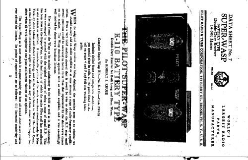
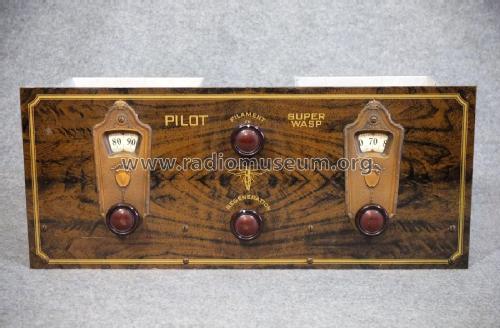
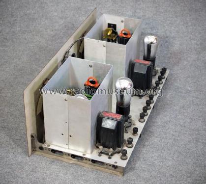
Super Wasp K-110
Pilot Electric Mfg. Co. (Radio Corp.); Brooklyn (NY)
- Country
- United States of America (USA)
- Manufacturer / Brand
- Pilot Electric Mfg. Co. (Radio Corp.); Brooklyn (NY)
- Year
- 1927
- Category
- Kit (Parts plus instruction) or building instructions only
- Radiomuseum.org ID
- 51957
-
- alternative name: Pilot Radio & Television || Pilot Radio and Tube || Pilot Radio Corporation
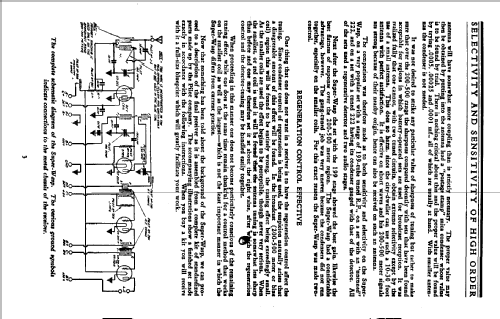
Click on the schematic thumbnail to request the schematic as a free document.
- Number of Tubes
- 4
- Main principle
- TRF with regeneration; 2 AF stage(s)
- Tuned circuits
- 2 AM circuit(s)
- Wave bands
- Broadcast plus more than 2 Short Wave bands.
- Power type and voltage
- Storage and/or dry batteries / -4.5; 6; 22,5; 45; 45; 45; x Volt
- Loudspeaker
- - For headphones or amp.
- Material
- Metal case
- from Radiomuseum.org
- Model: Super Wasp K-110 - Pilot Electric Mfg. Co. Radio
- Shape
- Chassis only or for «building in»
- Dimensions (WHD)
- 18 x 7.5 x 9.5 inch / 457 x 191 x 241 mm
- Notes
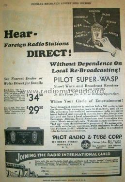
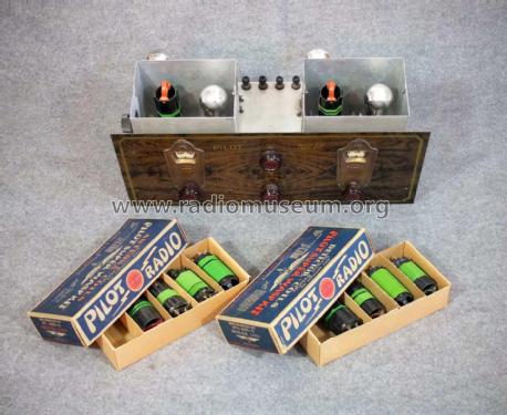
- Catalog is asking for identical Pilot tubes (sales promotion).
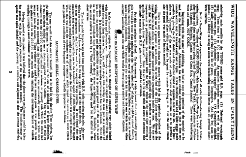
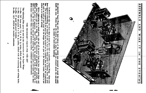
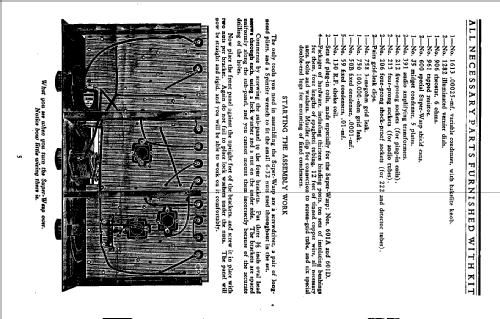
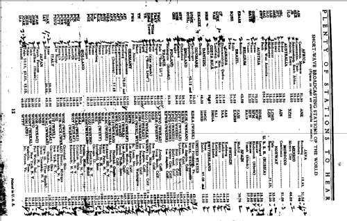
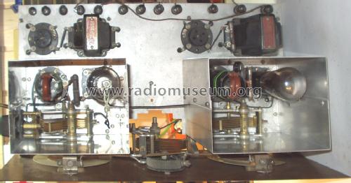
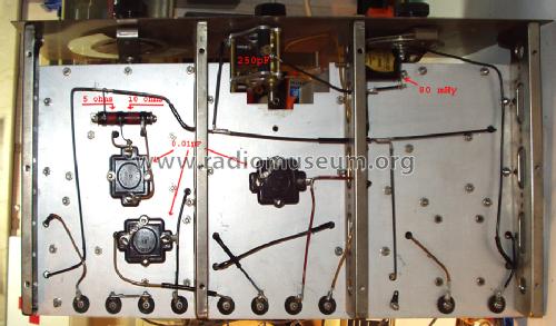
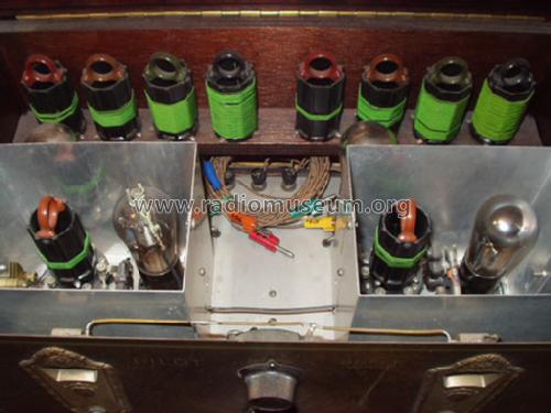
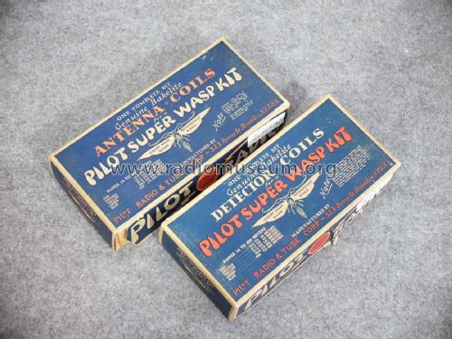
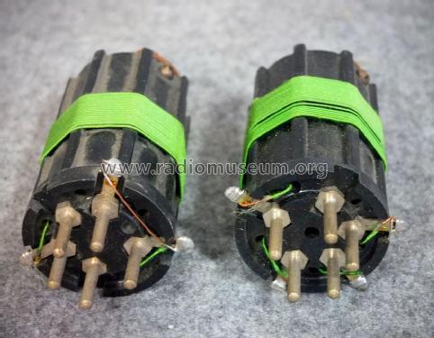
5 pairs of interchangeable coils for band selection. Catalog and assembly description of wave ranges (14.5-27 m; 26-50 m; 50-100 m; 100-200 m; 200-500 m) are not in accordance with reality, see photos.
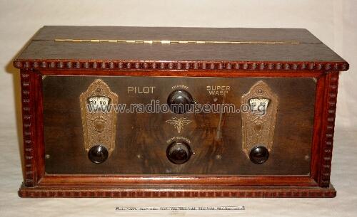
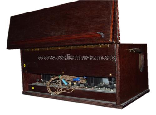
This was sold as a kit only. The cabinet in the photo was later custom built (1985).
The set can also be modified to use '99 tubes plus the '22. That requires an additional resistor and a separate power switch.
The date 1927 comes from a Pilot ad.
- Price in first year of sale
- 29.00 $
- External source of data
- Ernst Erb
- Source of data
- Radio Collector`s Guide 1921-1932
- Circuit diagram reference
- Rider's Perpetual, Volume 1 = 1931/1934 (for 1919-1931)
- Mentioned in
- Radio Manufacturers of the 1920's, Vol. 2 (Radio News June 1929)
- Literature/Schematics (1)
- Collector's Guide to Antique Radios (6th edition) (and: A Flick of the Switch)
- Other Models
-
Here you find 544 models, 271 with images and 408 with schematics for wireless sets etc. In French: TSF for Télégraphie sans fil.
All listed radios etc. from Pilot Electric Mfg. Co. (Radio Corp.); Brooklyn (NY)
Collections
The model Super Wasp is part of the collections of the following members.
Museums
The model Super Wasp can be seen in the following museums.
Forum contributions about this model: Pilot Electric Mfg.: Super Wasp K-110
Threads: 1 | Posts: 5
Hi Everyone,
I have recently acquired a Pilot Wasp Radio and I cannot seem to identify which model it is exactly. I think it may be a combination of several models.
It operates from 240V AC and has a filter power supply using an 80 rectifier.
The Valve lineup is 39 36 76 41 80.
It also came with a box of plugin coils.
The pictures of the radio are attached.
Attachments
- Pilot Wasp Front (50 KB)
- Pilot Wasp Top (64 KB)
- Pilot Wasp Bottom (72 KB)
- Pilot Wasp Coil Box (64 KB)
- Pilot Wasp Plugin Coils (62 KB)
- Pilot Wasp Document Cover (88 KB)
Gary Cowans, 13.May.14
