- Pays
- Etats-Unis
- Fabricant / Marque
- Pilot Electric Mfg. Co. (Radio Corp.); Brooklyn (NY)
- Année
- 1952 ??
- Catégorie
- Récepteur de télévision ou moniteur
- Radiomuseum.org ID
- 294018
-
- alternative name: Pilot Radio & Television || Pilot Radio and Tube || Pilot Radio Corporation
- No. de tubes
- 29
- Lampes / Tubes
- 12AT7 12AT7 12AT7 12AT7 12AT7 12AT7 12AT7 6AU6 6AU6 6AU6 6AU6 6AU6 6AL5 6AL5 6AQ5 6CB6 6C4 6S4 6AT6 6SN7 6CD6 6W4 1B3 1B3 6BA6 6BE6 5U4GB 16TP4
- Principe général
- Super hétérodyne avec étage HF
- Gammes d'ondes
- VHF/UHF (voir details en note)
- Tension / type courant
- Alimentation Courant Alternatif (CA) / 110 Volt
- Haut-parleur
- HP dynamique à aimant permanent + bobine mobile / Ø 8 inch = 20.3 cm
- Matière
- Boitier en bois
- De Radiomuseum.org
- Modèle: TV-164 - Pilot Electric Mfg. Co. Radio
- Forme
- Modèle de table générique
- Dimensions (LHP)
- 25 x 20 x 10 inch / 635 x 508 x 254 mm
- Remarques
-
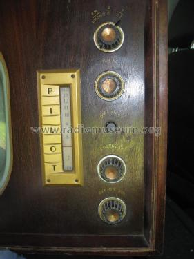
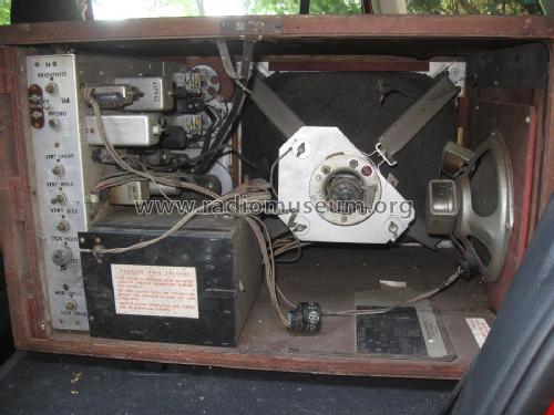
This is a Pilot television model TV-164. It covers channels 2 through 13 and the FM band 88 - 108 MHz. Channels 2 through 6 are in one band, channels 7 through 13 are another band, and the FM radio is a third band. The CRT tube is a 16TP4.
The schematic is found in Riders TV volume 6, pages 6-1 through 6-10.
The Rider TV Volume 6 pages 6-1 through 6-10 also cover models TV-127, TV-167A, and TV-191.TV-127 uses a 12LP4 CRT.
TV-164 uses a 16LP4 or 16XP4 CRT.
TV-167A uses a 16LP4 or 16XP4 CRT.
TV-191 uses a 19AP4 CRT.The television has 5 controls:
1. On/Off Volume
2. Contrast
3. Dial Light Button
4. Band Switch
A. FM/Phono
B. Channel 2-6
C. Channel 7-13
- Schémathèque (1)
- Riders TV Volume 6, pages 6-1 through 6-10
- Auteur
- Modèle crée par Jon Kummer. Voir les propositions de modification pour les contributeurs supplémentaires.
- D'autres Modèles
-
Vous pourrez trouver sous ce lien 544 modèles d'appareils, 273 avec des images et 412 avec des schémas.
Tous les appareils de Pilot Electric Mfg. Co. (Radio Corp.); Brooklyn (NY)


