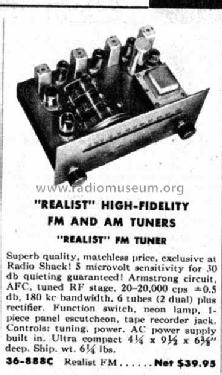
Realist FM Cat. No.= 36-888C
Radio Shack (Tandy, Realistic, Micronta); USA
- Produttore / Marca
- Radio Shack (Tandy, Realistic, Micronta); USA
- Anno
- 1955
- Categoria
- Radio (o sintonizzatore del dopoguerra WW2)
- Radiomuseum.org ID
- 155185
Clicca sulla miniatura dello schema per richiederlo come documento gratuito.
- Numero di tubi
- 6
- Principio generale
- Supereterodina con stadio RF; ZF/IF 10700 kHz
- N. di circuiti accordati
- 12 Circuiti Mod. Freq. (FM)
- Gamme d'onda
- Solo modulazione di frequenza (FM)
- Tensioni di funzionamento
- Alimentazione a corrente alternata (CA) / 117 Volt
- Altoparlante
- - Per cuffie o amplificatori esterni
- Materiali
- Mobile di metallo, valvole visibili
- Radiomuseum.org
- Modello: Realist FM Cat. No.= 36-888C - Radio Shack Tandy, Realistic,
- Forma
- Chassis o in scatola da montaggio
- Dimensioni (LxAxP)
- 8 x 6 x 4 inch / 203 x 152 x 102 mm
- Annotazioni
-
First house-branded FM tuner introduced by Radio Shack in 1955 as the Realist FM model. Claimed sensitivity was 5uV for 30dB or quieting. The tuner was made by Harman Kardon with Radio Shack specifications, and is very similiar to the Harman Kardon Counterpoint model A-400 from 1956. The A-400 has one extra 6AU6 IF stage, an output 12AU7 audio preamp and a tuning meter. The Realist FM was well reviewed in the HIFI magazines of 1955. Wood case was optional and is now rarely found.
- Peso netto
- 1.362 kg / 3 lb 0 oz (3 lb)
- Prezzo nel primo anno
- 39.95 USD
- Bibliografia
- Radio Shack Catalog (1955, page 165)
- Autore
- Modello inviato da Joe Sousa. Utilizzare "Proponi modifica" per inviare ulteriori dati.
- Altri modelli
-
In questo link sono elencati 1331 modelli, di cui 1214 con immagini e 163 con schemi.
Elenco delle radio e altri apparecchi della Radio Shack (Tandy, Realistic, Micronta); USA
Discussioni nel forum su questo modello: Radio Shack Tandy,: Realist FM Cat. No.= 36-888C
Argomenti: 2 | Articoli: 3
Fellow radiophiles,
I have a special fondness for Radio Shack's first house branded Realist tuner. Now I own two of these tuners. This is quite unusual for me. The first tuner had been somewhat modified in that the phono pass-through connection was removed. When I came across one of these tuners at a low price with the very rare wooden case, and the original circuitry, I decided to buy it.
But this "original" condition set had serious trouble at the LO (Local Oscillator). There were portions of the tuning band where it would completely fade out. After comparing my two tuners, I noticed a slightly different LO and RF coil design for the two tuners.
The new tuner with the faulty LO:
The old tuner with a good working LO:
The new tuner with a new 3 turn LO coil:
The LO now works fine with the new 3 turn coil. The coil was bent in place for correct alignment at the low end fo the dial. The existing trim capacitor in parallel with the LO coil was used to align the high end of the dial.
In a way, I was lucky to have to sets to compare. Perhaps the old coil was original, and someone added the capacitor at the tap. I don't remember if I removed the cap to see if that was the cause of the LO trouble. I reasoned that the LO dropouts might have been caused by a lower Q in the 4 turn coil that was scrunched against the chassis. I will never know for sure what was the real cause: bad coil design, or spurious capacitor.
Regards,
-Joe
Joe Sousa, 22.Feb.10
Hello Radiophiles,
This very nice tuner has a tendency to oscillate if the FM antenna twin-lead wire is brought too close to the 6U8 RF front end preamp pentode.

The 6U8 is not shielded, and the input antenna connection is single ended. This means that a twin lead wire connection will be "hot", and will be able to radiate or receive signal.
The proper connection for a 300 Ohm twin lead is with a balanced transformer input.
Balanced input has both inputs equally active, so that any signal arriving at the twin lead is cancelled.
The single ended 300 Ohm connection useful if some of the expected use is to use short length of wire as the antenna, or if the antenna is the power cord that is capacitivelly coupled with a metal clip.

An isolation 1:1 VHF transformer at the antenna terminals can cure the problem.
Or just keep the twin lead away from the left side of the chassis as shown by the arrow. Also remember that the bottom of the chassis is open, and can be a path for undesired feedback.
I added a piece of discarded PCB as a groundedshield to the bottom of my tuner.
Regards,
-Joe
Joe Sousa, 20.Oct.09


