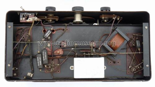
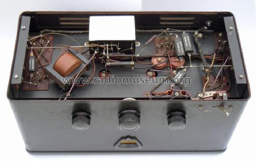
WF3 Zweiweg-Gleichrichter
Radione (RADIO Nikolaus Eltz); Wien
- Country
- Austria
- Manufacturer / Brand
- Radione (RADIO Nikolaus Eltz); Wien
- Year
- 1931/1932
- Category
- Broadcast Receiver - or past WW2 Tuner
- Radiomuseum.org ID
- 10207
Click on the schematic thumbnail to request the schematic as a free document.
- Number of Tubes
- 4
- Main principle
- TRF with regeneration
- Tuned circuits
- 2 AM circuit(s)
- Wave bands
- Broadcast only (MW).
- Power type and voltage
- Alternating Current supply (AC) / 110 - 220 Volt
- Loudspeaker
- - This model requires external speaker(s).
- Material
- Metal case
- from Radiomuseum.org
- Model: WF3 [Zweiweg-Gleichrichter] - Radione RADIO Nikolaus Eltz;
- Shape
- Tablemodel, Box - most often with Lid (NOT slant panel).
- Dimensions (WHD)
- 375 x 205 x 195 mm / 14.8 x 8.1 x 7.7 inch
- Notes
-
Fernempfänger, Zweikreiser,
HF-Vorstufe mit Tetrode,
Audion mit Rückkopplung mit Triode
NF-Endstufe mit Pentode
Netzteil mit ZweiweggleichrichtungEs existiert eine (frühere) Version des Radione WF3 mit Einweg-Gleichrichter und mit anderem Chassisaufbau.
Im Prospekt der O.Ö. Elektrobau A.G. über die Neuheitem aus 1931/1932 wird einen Preis von 332 ATS genannt.
- Price in first year of sale
- 290.00 ATS
- External source of data
- E. Erb 3-907007-36-0
- Source of data
- Radiokatalog Band 2, Ernst Erb
- Mentioned in
- -- Schematic
- Literature/Schematics (1)
- -- Original prospect or advert (O.Ö. Elektrobau A.G. über die Neuheiten 1931/1932)
- Other Models
-
Here you find 520 models, 363 with images and 321 with schematics for wireless sets etc. In French: TSF for Télégraphie sans fil.
All listed radios etc. from Radione (RADIO Nikolaus Eltz); Wien
Collections
The model is part of the collections of the following members.
Forum contributions about this model: Radione RADIO: WF3
Threads: 2 | Posts: 4
Liebe Sammlerkollegen,
ich benötige Eure Hilfe bei der Zuordnung meines Radione WF3:
1. anstelle der Gleichrichterröhre lt. Plan und Aufzeichnung hat mein Gerät nur 3 Stifte im Sockel (möglicherweise für eine RGN354 oder RGN 564?)
2. die Anordnung der Bauteile auf der Ober- und Unterseite sind nicht identisch wie auf den Bildern der Beschreibung im RM.
3. zusätzlich ist eine Drosselspule verbaut:
4. am linken Antennenanschluss sind 6 Buchsen (nicht so im Schaltplan) verwendet worden.
Im Inneren ist die Zuleitung zur LA (Lichtantenne) gekappt worden.
Wer kann mir weiterhelfen, auch ev. mit einem anderen Schaltplan.
Viele Grüße
Horst Schneider
Mit der Röhrenbestückung RENS1214, REN904, RES164, RGN 354 läuft das Radio!
Attachments
- Radione WF3 (155 KB)
- P1040515-1 (175 KB)
- P1040516-1 (167 KB)
- P1040517-1 (138 KB)
- P1040518-1 (165 KB)
Horst Schneider, 07.Sep.15
Wilfried Hofmüller, 17.Dec.02


