- País
- Estados Unidos
- Fabricante / Marca
- RCA (RCA Victor Co. Inc.); New York (NY)
- Año
- 1937
- Categoría
- Radio - o Sintonizador pasado WW2
- Radiomuseum.org ID
- 53766
-
- alternative name: RCA Manufacturing || Victor Talking Machine


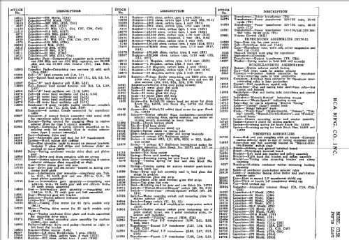


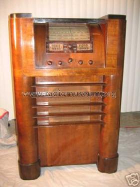


RCA 813K chassis

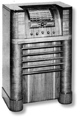
Scanned from the Radio Retailing June 1937.

Scanned from the Radio Retailing June 1937.

Ebay Seller willeezwarez Item 261011720249


RECONSTRUCTED LABEL

RECONSTRUCTED LABEL

RECONSTRUCTED LABEL
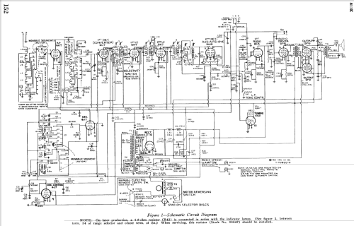
Haga clic en la miniatura esquemática para solicitarlo como documento gratuito.
- Numero de valvulas
- 13
- Principio principal
- Superheterodino con paso previo de RF; ZF/IF 460 kHz
- Gama de ondas
- OM y más de dos OC
- Tensión de funcionamiento
- Red: Corriente alterna (CA, Inglés = AC) / 105-125 Volt
- Altavoz
- Altavoz electrodinámico (bobina de campo) / Ø 12 inch = 30.5 cm
- Potencia de salida
- 15 W (unknown quality)
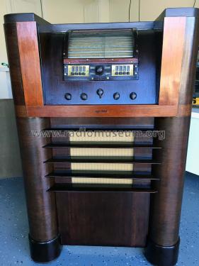
- Material
- Madera
- de Radiomuseum.org
- Modelo: 813K - RCA RCA Victor Co. Inc.; New
- Forma
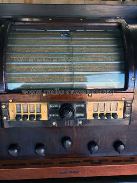
- Consola con botonera.
- Ancho, altura, profundidad
- 28.625 x 43 x 17 inch / 727 x 1092 x 432 mm
- Anotaciones
- BC and 4xSW.
There is also the similar canadian model 813K.
- Ext. procedencia de los datos
- Ernst Erb
- Procedencia de los datos
- The Radio Collector's Directory and Price Guide 1921 - 1965
- Referencia esquema
- Rider's Perpetual, Volume 9 = 1938 and before
- Mencionado en
- Collector's Guide to Antique Radios 4. Edition
- Documentación / Esquemas (1)
- Pre-War Consoles
- Documentación / Esquemas (2)
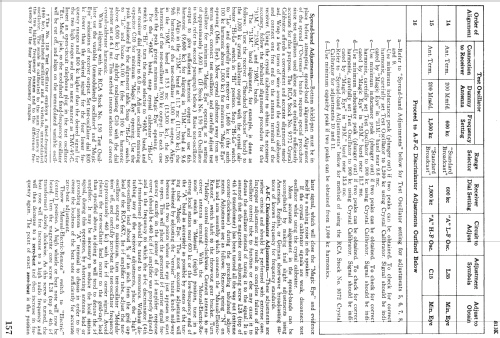
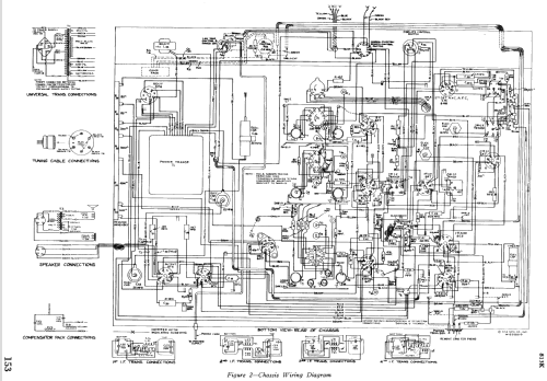
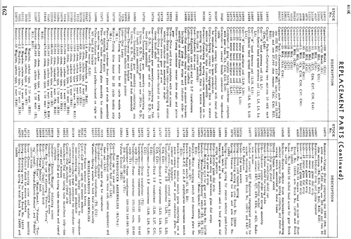
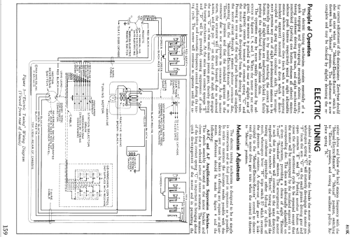
- RCA Victor Service Notes for 1937 (RCA Redbook)
- Documentación / Esquemas (3)
- Radio Retailing (Radio & Television R.) (June 1937.)
- Otros modelos
-
Donde encontrará 5134 modelos, 3237 con imágenes y 4174 con esquemas.
Ir al listado general de RCA (RCA Victor Co. Inc.); New York (NY)
Colecciones
El modelo 813K es parte de las colecciones de los siguientes miembros.
Contribuciones en el Foro acerca de este modelo: RCA RCA Victor Co.: 813K
Hilos: 1 | Mensajes: 9
I'm restoring an 813K and had a few questions, the cabinet is finished and now working on the electronics. The bezel was my greatest challenge it had shrunk and twisted over time I guess or maybe was left in the sun. I completely re-fabricated one out of wood except for the lower part. Lettering for the knobs was not visible for the two left knobs. Far left is power 2nd from left not sure.So looking for the exact wording for the knobs? Wood working is my forte electronics not so much.
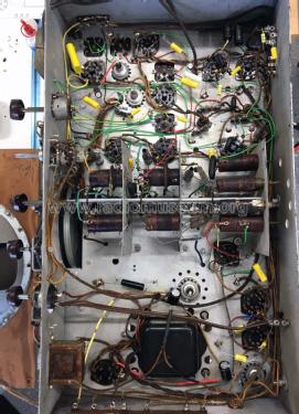
I have replaced all the capacitors and found one electrolyte C56 (20mfd) with positive going to ground. That doesn't seem right to me but it appears to be from the factory. Does that seem right to you?
The schematics that I have do not indicate polarity on any of the electrolytes. C53 (25mfd), C54 (25mfd), C55 & C57 (both 16mfd) were in cans. C53 & C54 had tabs between non-conductive wafers and wires were connected to the tabs. Unfortunately I didn't pay attention to how these wafers were placed, but assume they were to isolate the can from the tab. So my question is this: with only one lead coming out of the top of these cans (which i assume to be +) where does the negative lead go? My assumption is to the tabs? But from inside the can how does the negative lead get to the tabs?
On the top of the drive motor for electronic tuning there is (what appears to be a capacitor) with absolutely no markings on it and I can't find it on the schematic anywhere. but again my electronic knowledge leaves a lot to be desired.
I know this a lot but would appreciate any help anyone can offer.
Jim Hochstetler
361-442-7435
Headline edited and post moved to model
James Hochstetler, 11.Nov.21