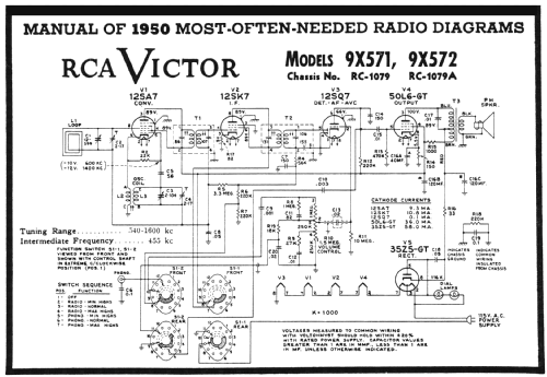
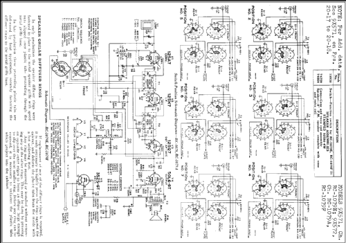
9-X-571 Ch= RC-1079
RCA (RCA Victor Co. Inc.); New York (NY)
- Pays
- Etats-Unis
- Fabricant / Marque
- RCA (RCA Victor Co. Inc.); New York (NY)
- Année
- 1949
- Catégorie
- Radio - ou tuner d'après la guerre 1939-45
- Radiomuseum.org ID
- 54105
-
- alternative name: RCA Manufacturing || Victor Talking Machine
Beitman


Rider
Rider


Complete Restoration
Complete Restoration
Complete Restoration

Complete Restoration

Complete Restoration

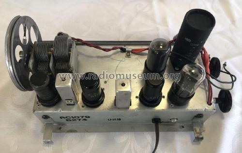
By Courtesy Of EBAY User: akachuck

Copy gen. von Art Hoch Radio Attic
By courtesy of William Kendrick, USA

By courtesy of William Kendrick, USA


Q = Ebay objnr : 150121826921


By Courtesy Of EBAY User: akachuck

By Courtesy Of EBAY User: akachuck

By Courtesy Of EBAY User: akachuck

By Courtesy Of EBAY User: akachuck

By Courtesy Of EBAY User: akachuck

By Courtesy Of EBAY User: akachuck


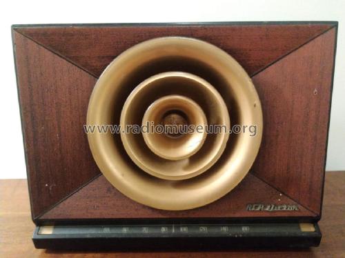
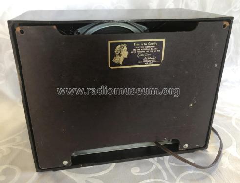
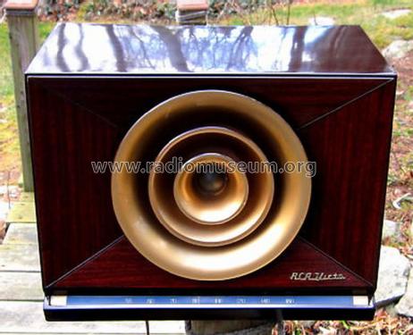
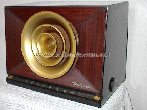
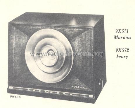
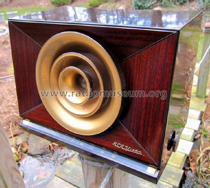
RCA Victor 9-X-571.
Cliquez sur la vignette du schéma pour le demander en tant que document gratuit.
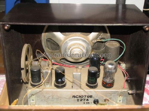
- No. de tubes
- 5
- Principe général
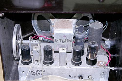
- Super hétérodyne (en général); FI/IF 455 kHz; 2 Etage(s) BF
- Circuits accordés
- 6 Circuits MA (AM)
- Gammes d'ondes
- PO uniquement
- Tension / type courant
- Appareil tous courants (CA / CC) / 115 Volt
- Haut-parleur
- HP dynamique à aimant permanent + bobine mobile / Ø 8 inch = 20.3 cm
- Puissance de sortie
- 1.75 W (qualité inconnue)
- Matière
- Boitier en bakélite
- De Radiomuseum.org
- Modèle: 9-X-571 Ch= RC-1079 - RCA RCA Victor Co. Inc.; New
- Forme
- Modèle de table sans poussoirs, modèle cheminée
- Dimensions (LHP)
- 320 x 240 x 210 mm / 12.6 x 9.4 x 8.3 inch
- Remarques
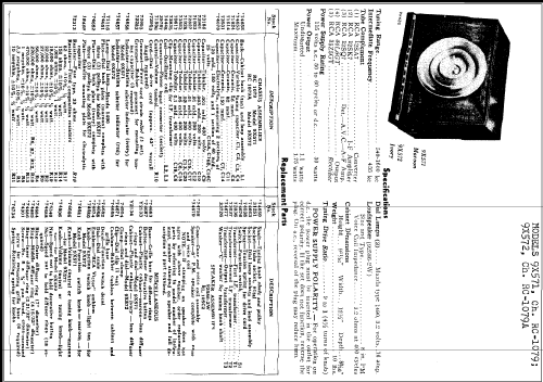
- RCA Victor Model 9X-571 shows the color: maroon. Similar model 5-X-572 (#5X572) is in ivory. Dial lamps: 2 Mazda type 1490, 3.2V, 0.16 amp.
- Poids net
- 4.6 kg / 10 lb 2.1 oz (10.132 lb)
- Source extérieure
- Ernst Erb
- Source du schéma
- Rider's Perpetual, Volume 20 covering 1950
- Littérature
- Collector's Guide to Antique Radios 4. Edition
- Schémathèque (1)
- RCA Victor Instruments Service Notes 1949
- D'autres Modèles
-
Vous pourrez trouver sous ce lien 5134 modèles d'appareils, 3237 avec des images et 4171 avec des schémas.
Tous les appareils de RCA (RCA Victor Co. Inc.); New York (NY)
Collections
Le modèle 9-X-571 fait partie des collections des membres suivants.
Contributions du forum pour ce modèle: RCA RCA Victor Co.: 9-X-571 Ch= RC-1079
Discussions: 1 | Publications: 4
Static during reception with this model is often caused by internal leakage in the IF transformers caused by silver creap in the internal capacitors that causes leakage current between the primary and secondary.
Note: use care when desoldering and soldering to these IF transformer pins because excessive heat will cause the plastic base surrounding the pin to melt and the pin to loosen which can cause internal connections to break.
This leakage can be checked by disconnecting the secondary (both terminals) of the IF transformer. Test one transformer at a time. Temporarily connect the two wires together that were disconnected from the transformer secondary so the remaining radio circuitry will not be an open circuit. Connect a high impedance DC voltmeter, such as a vacuum tube voltmeter or a digital voltmeter, to either of the disconnected secondary terminals. Turn on the radio and check for the presence of any DC voltage reading on the meter. This might be a jumpy reading. A transformer with good capacitors will not have any voltage during this test.
If leakage is found it can usually be eliminated by disassembling the IF transformer and making repairs. Sometimes careful visual inspection will show black wiskers on the mica capacitor sheet between the primary and secondary sides which can be scraped away. Sometimes the mica sheets can be carefully cut or broken to separate the primary side from the secondary side. Sometimes the mica sheet capacitors must be disconnected or removed and replaced by temperature-stable ceramic or mica capacitors.
Paul Moyer, 24.Jan.07