Signalverfolger
RIM bzw. Radio-RIM; München
- Paese
- Germania
- Produttore / Marca
- RIM bzw. Radio-RIM; München
- Anno
- 1958–1965 ??
- Categoria
- Strumento da laboratorio
- Radiomuseum.org ID
- 101937
-
- Brand: Radiola-Industrie GmbH
Clicca sulla miniatura dello schema per richiederlo come documento gratuito.
- Numero di tubi
- 3
- Numero di transistor
- Semiconduttori
- Tr.Gl.=Metal-rectif.
- Principio generale
- Amplificatore audio; 4 Stadi BF
- Gamme d'onda
- - senza
- Tensioni di funzionamento
- Alimentazione a corrente alternata (CA) / 110/220 Volt
- Altoparlante
- AP magnetodinamico (magnete permanente e bobina mobile)
- Potenza d'uscita
- 0.5 W (qualità ignota)
- Materiali
- Mobile di metallo
- Radiomuseum.org
- Modello: Signalverfolger - RIM bzw. Radio-RIM; München
- Forma
- Soprammobile con qualsiasi forma (non saputo).
- Annotazioni
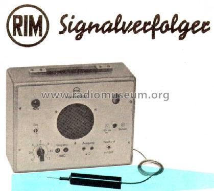
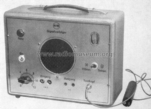
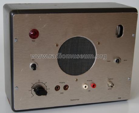
- Vierstufiger Signalverfolger mit Tastkopf für NF und HF. 1958 nur als Bausatz.
Fertiggerät (29814) 1965 für DM 185
- Prezzo nel primo anno
- 135.00 DM
- Bibliografia
- -- Original prospect or advert (RIM Bastelbuch 1965)
- Autore
- Modello inviato da Otto Frosinn. Utilizzare "Proponi modifica" per inviare ulteriori dati.
- Altri modelli
-
In questo link sono elencati 313 modelli, di cui 299 con immagini e 243 con schemi.
Elenco delle radio e altri apparecchi della RIM bzw. Radio-RIM; München
Collezioni
Il modello Signalverfolger fa parte delle collezioni dei seguenti membri.
Discussioni nel forum su questo modello: RIM bzw. Radio-RIM;: Signalverfolger
Argomenti: 2 | Articoli: 4
Dear friends,
Merry Christmas and a Happy New Year
Rolf
1) The Munic company RIM (Radio Industrie München), like Heathkit or Knight, is today part of the Conrad electronic empire
Further enclosures (figures) see here
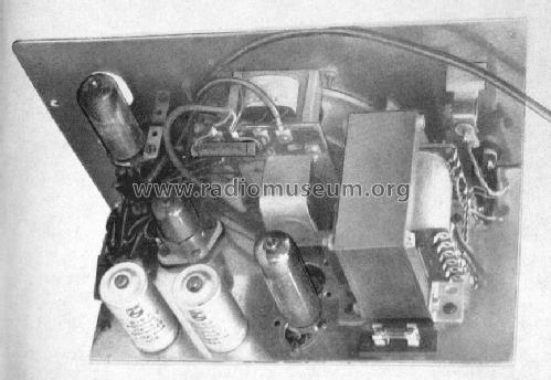
as a pupil I "devoured" the Heinz Richter books in which many schematics of Radio RIM1 kits were discussed among other things. I was fascinated of e.g. the "signal tracer", probably because of the strange term and the two figures shown in the book which I added on the equipment sheet.
I could not afford or did not want to buy the kit, could also be that it was not offered any longer at the beginning of the seventies (of the last century). However, I had already collected many component parts during my life as hobbyist, and now I got a cannibalized casing and the power and the output transformer from a small EMUD reverberation amplifier. This should be sufficient to build such a signal tracer with parts of my own, I thought for me and started the realization.
"Printed circuit boards" (PCBs) were a MUST HAVE at that time if you did not want to be classified old fashioned by the "dear" colleagues who only worked with solid states / semiconductors and did not understand my "tube maniac" behaviour. A little bit more self-confidence or with today's state of experience one would qualify such approach as nonsense: Laying-out the board, exposing to light, chemical etching, washing, drilling the holes, such a lot of work for only one single apparatus!
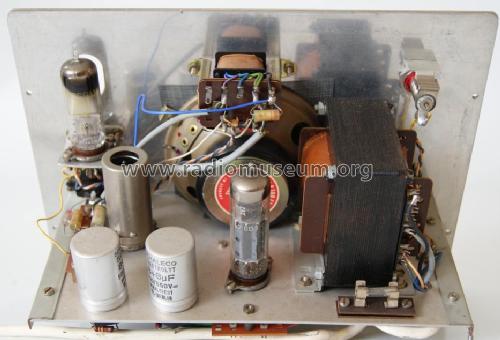
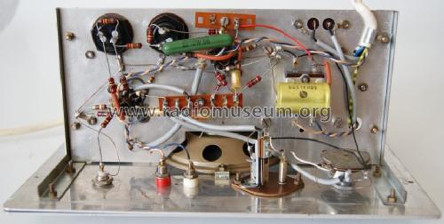
The casing was provided with a new front panel made of aluminium. After drilling it was labelled with rub-on-letters ("Letraset") and sealed with "Plastic spray 70". The front panel also serves as a "rack" (chassis) for the component parts including the PCB and with the exception of the transformers and the loudspeaker.
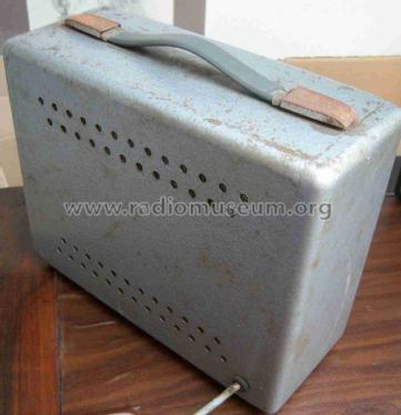
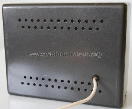
For this part half a million of small holes were drilled into the rear side of the casing. After that they were covered by a special type of cloth. I changed the original design regarding the tube equipment, instead of ECL 82 the "more modern" ECL 86 was used . And my apparatus was not provided with the optical indicator tube EM 80 (magic eye) because this was not necessary in my opinion.
In 1978 an important change was carried out. The PCB-part with the first and second amplifier stage (ECC 83) was cutted and replaced by a sticked-on new two-layer PCB. The top layer serves as an additional screen. I cannot remember exactly why but I guess because of radiated mains hum from the power transformer.

Today, the performance seems still very well, but for a satisfying sound it is necessary to use an external, proper speaker. The built-in one sounds "metallic" and acts as a makeshift.
I could not afford or did not want to buy the kit, could also be that it was not offered any longer at the beginning of the seventies (of the last century). However, I had already collected many component parts during my life as hobbyist, and now I got a cannibalized casing and the power and the output transformer from a small EMUD reverberation amplifier. This should be sufficient to build such a signal tracer with parts of my own, I thought for me and started the realization.
"Printed circuit boards" (PCBs) were a MUST HAVE at that time if you did not want to be classified old fashioned by the "dear" colleagues who only worked with solid states / semiconductors and did not understand my "tube maniac" behaviour. A little bit more self-confidence or with today's state of experience one would qualify such approach as nonsense: Laying-out the board, exposing to light, chemical etching, washing, drilling the holes, such a lot of work for only one single apparatus!
The casing was provided with a new front panel made of aluminium. After drilling it was labelled with rub-on-letters ("Letraset") and sealed with "Plastic spray 70". The front panel also serves as a "rack" (chassis) for the component parts including the PCB and with the exception of the transformers and the loudspeaker.
For this part half a million of small holes were drilled into the rear side of the casing. After that they were covered by a special type of cloth. I changed the original design regarding the tube equipment, instead of ECL 82 the "more modern" ECL 86 was used . And my apparatus was not provided with the optical indicator tube EM 80 (magic eye) because this was not necessary in my opinion.
In 1978 an important change was carried out. The PCB-part with the first and second amplifier stage (ECC 83) was cutted and replaced by a sticked-on new two-layer PCB. The top layer serves as an additional screen. I cannot remember exactly why but I guess because of radiated mains hum from the power transformer.
Today, the performance seems still very well, but for a satisfying sound it is necessary to use an external, proper speaker. The built-in one sounds "metallic" and acts as a makeshift.
Merry Christmas and a Happy New Year
Rolf
1) The Munic company RIM (Radio Industrie München), like Heathkit or Knight, is today part of the Conrad electronic empire
Further enclosures (figures) see here
Rolf Nickel, 21.Dec.07
Liebe Leser,
als Schüler habe ich die Heinz-Richter-Bücher "verschlungen", in denen unter Anderem die Schaltungen vieler Radio-RIM-Bausatzgeräte besprochen wurden. Fasziniert hat mich z. B. der "Signalverfolger", wahrscheinlich auch wegen des fremdartigen Begriffs und der im Buch gezeigten Abbildungen, die ich auf der Geräteseite ergänzt habe.
Den Bausatz konnte oder wollte ich mir nicht leisten, wahrscheinlich wurde er Anfang der 70er Jahre (des vorigen Jahrhunderts) auch gar nicht mehr angeboten. Aber im Laufe meiner Basteltätigkeit hatte ich schon einiges an Einzelteilen gesammelt, und nun kamen noch ein ausgeschlachtetes Gehäuse und der Netz- und Ausgangstrafo eines kleinen EMUD-Hallverstärkers hinzu. Das müsste ausreichen, um einen solchen Signalverfolger mit eigenen Teilen zu bauen, dachte ich mir und ging an die Verwirklichung.
Damals waren "gedruckte Schaltungen" ein absolutes Muss, wenn man vor den "lieben" Kollegen, die nur noch mit Halbleitern bastelten und mich wegen meines "Röhrenvogels" veräppelten, bestehen wollte. Bei etwas mehr Selbstbewusstsein bzw. mit heutigem Kenntnisstand kann man das nur als Unsinn bezeichnen: Platine kleben, belichten, ätzen, waschen, bohren, und das alles für ein einziges Exemplar !
Das Gehäuse erhielt eine neue Frontplatte aus Aluminium. Nach dem Bohren wurde sie mit "Letraset"-Abreibe-Buchstaben beschriftet und mit "Plastik-Spray 70" versiegelt. Die Frontplatte dient auch als Träger ("Gestell") für die Einzelteile ausser dem Lautsprecher und den Transformatoren.
In die Rückseite des Gehäuses wurde "eine halbe Million" kleiner Löcher für den Lautsprecher-Schallaustritt gebohrt und mit Bespannstoff verkleidet. Bei der Röhrenbestückung bin ich vom Original abgewichen, statt einer ECL 82 wurde die "modernere" ECL 86 verwendet. Außerdem erhielt das Gerät keine optische Anzeige EM 80 ("magischer Fächer"), weil ich das für unnötig hielt.
1978 wurde eine wichtige Änderung durchgeführt. Der Teil der Leiterplatte mit der ersten und zweiten Verstärkerstufe ECC 83 wurde abgeschnitten und durch eine doppelt kaschierte ersetzt. Die obere zweite Lage dient als zusätzliche Schirmung. Ich weiß nicht mehr genau, warum ich das tat. Wahrscheinlich zur Minimierung von Brummeinstreuungen.

Das Ergebnis kann sich auch heute noch sehen und hören lassen, Letzteres aber nur bei Benutzung eines externen, ordentlichen Lautsprechers. Der eingebaute klingt natürlich "nach Blech" und ist ein Notbehelf.
Frohe Weihnachten wünscht
Rolf Nickel
Den Bausatz konnte oder wollte ich mir nicht leisten, wahrscheinlich wurde er Anfang der 70er Jahre (des vorigen Jahrhunderts) auch gar nicht mehr angeboten. Aber im Laufe meiner Basteltätigkeit hatte ich schon einiges an Einzelteilen gesammelt, und nun kamen noch ein ausgeschlachtetes Gehäuse und der Netz- und Ausgangstrafo eines kleinen EMUD-Hallverstärkers hinzu. Das müsste ausreichen, um einen solchen Signalverfolger mit eigenen Teilen zu bauen, dachte ich mir und ging an die Verwirklichung.
Damals waren "gedruckte Schaltungen" ein absolutes Muss, wenn man vor den "lieben" Kollegen, die nur noch mit Halbleitern bastelten und mich wegen meines "Röhrenvogels" veräppelten, bestehen wollte. Bei etwas mehr Selbstbewusstsein bzw. mit heutigem Kenntnisstand kann man das nur als Unsinn bezeichnen: Platine kleben, belichten, ätzen, waschen, bohren, und das alles für ein einziges Exemplar !
Das Gehäuse erhielt eine neue Frontplatte aus Aluminium. Nach dem Bohren wurde sie mit "Letraset"-Abreibe-Buchstaben beschriftet und mit "Plastik-Spray 70" versiegelt. Die Frontplatte dient auch als Träger ("Gestell") für die Einzelteile ausser dem Lautsprecher und den Transformatoren.
In die Rückseite des Gehäuses wurde "eine halbe Million" kleiner Löcher für den Lautsprecher-Schallaustritt gebohrt und mit Bespannstoff verkleidet. Bei der Röhrenbestückung bin ich vom Original abgewichen, statt einer ECL 82 wurde die "modernere" ECL 86 verwendet. Außerdem erhielt das Gerät keine optische Anzeige EM 80 ("magischer Fächer"), weil ich das für unnötig hielt.
1978 wurde eine wichtige Änderung durchgeführt. Der Teil der Leiterplatte mit der ersten und zweiten Verstärkerstufe ECC 83 wurde abgeschnitten und durch eine doppelt kaschierte ersetzt. Die obere zweite Lage dient als zusätzliche Schirmung. Ich weiß nicht mehr genau, warum ich das tat. Wahrscheinlich zur Minimierung von Brummeinstreuungen.
Das Ergebnis kann sich auch heute noch sehen und hören lassen, Letzteres aber nur bei Benutzung eines externen, ordentlichen Lautsprechers. Der eingebaute klingt natürlich "nach Blech" und ist ein Notbehelf.
Frohe Weihnachten wünscht
Rolf Nickel
Allegati
- Aussen_Front (51 KB)
- Innen_gehaeuse (73 KB)
- Gehaeuse_Rueckseite (66 KB)
Rolf Nickel, 21.Dec.07


