UA-345 (UA345-X)
SABA; Villingen
- País
- Alemania
- Fabricante / Marca
- SABA; Villingen
- Año
- 1954/1955
- Categoría
- Radio - o Sintonizador pasado WW2
- Radiomuseum.org ID
- 75660
-
- Brand: Schwer & Söhne, GmbH


Eigenes Gerät

Gerät mit abgenommener Rückwand.

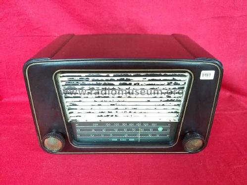
Front


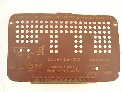
Rear cover


My own collection


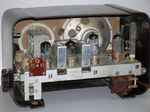


Scan der Rückwand
Haga clic en la miniatura esquemática para solicitarlo como documento gratuito.
- Numero de valvulas
- 4
- Principio principal
- Superheterodino en general
- Número de circuitos sintonía
- 6 Circuíto(s) AM
- Gama de ondas
- OM y dos OC
- Tensión de funcionamiento
- Red: Aparato AC/DC. / 117 / 220 Volt
- Altavoz
- Altavoz dinámico (de imán permanente) / Ø 14 cm = 5.5 inch
- Material
- Bakelita
- de Radiomuseum.org
- Modelo: UA-345 - SABA; Villingen
- Forma
- Sobremesa de cualquier forma, detalles no conocidos.
- Ancho, altura, profundidad
- 290 x 190 x 180 mm / 11.4 x 7.5 x 7.1 inch
- Anotaciones
- The SABA UA345-X (schematic, 5372-3000b of date June 1954) or UA-345 (back board) is a typical export model. According to the journal "Funk-Fachhändler" 1954, page 108 (with a picture) and page 116 (text) the UA-345 has been introduced at the "Hannover Messe" 1954.
- Peso neto
- 2.8 kg / 6 lb 2.7 oz (6.167 lb)
- Autor
- Modelo creado por Mario Coelho. Ver en "Modificar Ficha" los participantes posteriores.
- Otros modelos
-
Donde encontrará 1649 modelos, 1507 con imágenes y 1189 con esquemas.
Ir al listado general de SABA; Villingen
Colecciones
El modelo es parte de las colecciones de los siguientes miembros.
Contribuciones en el Foro acerca de este modelo: SABA; Villingen: UA-345
Hilos: 3 | Mensajes: 24
Dear members,
I have not yet been able to resolve how the existing schematic resolves the high plate voltages developed for the radio without the netz trafo, and no full-wave rectifier, to act as voltage doubler.
The schematic depicts 196Vfor the mixer plate; and 170V for the UAF plate, and the 215V for the power pentode plate.
Is there a possibility that the UY41 rectifier is actually configured very much like some of the erarly CY1 tubes produced - which were in fact "dual diode rectifier" capable.
Our esteemed emeritus engineer Hans Knoll has stated that Robert Sarbell occasionally finds some peculiar receivers!
If there is additional technical data that was available when these variant models were introduced by Mario, and inferred from the Notes section, could some member please enlighten me?
Respectfully,
Robert Sarbell
Nnote: I am aware of the inner electrode connections between pins 4,6, and 7 for the UY41, and this tube can be adapted for different transformerless power sources.
Robert Sarbell † 22.3.22, 18.Mar.11
Hello RMO members,
As Herr Knoll mentioned in the 2nd posting above, it seems as though I was most fortunate to win on ebaY one of the dwarf-sized export models, SN 54/832516, and have discovered the intermittent to weak reception on the SWII and SWI bands are probably related to the failed small antenna coil on the terminal board at the rear chassis.
I have had to unwind one of the 2 sections wound on the sub-miniature coil.
I beileve it may be near impossible to find another "parts chassis" for this radio. Therefore, I respectfully ask for assistance to determine the wire gauge (or size in fractional millimeters) to rewind the lost wire.
I removed 96 inches of the wire, but it had several serious kinks and will need to be "re-wound".
I am aware of the 22, 26, and 30 gauge spools for winding coils.
I also have not seen any reference to the ratings for the antenna coil on the schematic.
I would be most grateful if some member is aware of this issue.
Respectfully,
Robert Sarbell
Anexos
- Antenna coil (102 KB)
Robert Sarbell † 22.3.22, 12.Mar.11
I had recently upload a new model SABA UA-345. It is in my collection.
http://www.radiomuseum.org/dsp_modell.cfm?model_id=75660

I don't know much about it. I've not its schematic and I don't know its IF value. May be 452kc/s? It has only two IFTs, but it has a lot of RF adjustment screws. I'm not sure they are rightly tuned. It works but it can´t receive any broadcasting station.
Do you have any information about it?
It also has one resistor in series in its mains dropper circuit. It has a very high value 10KOhms. That seems to be a thermistor. Do you think possible it is an original component in the years of 40/50 or it is a "recent inovation"?
Best Regards
Mário
EE: I have put an empty line between the two pictures. Now the frame should not anymore "explode".
Mario Coelho, 13.Jan.05