Spezialsuper 51 SB502GW
Siemens (& Halske, -Schuckert Werke SSW, Electrogeräte); Berlin, München
- Hersteller / Marke
- Siemens (& Halske, -Schuckert Werke SSW, Electrogeräte); Berlin, München
- Jahr
- 1950/1951
- Kategorie
- Rundfunkempfänger (Radio - oder Tuner nach WW2)
- Radiomuseum.org ID
- 5233


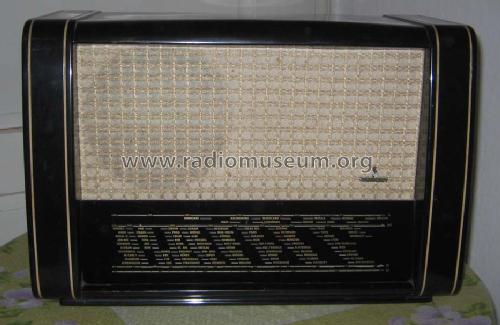
Siemens Spezial-Super 51GW Front2
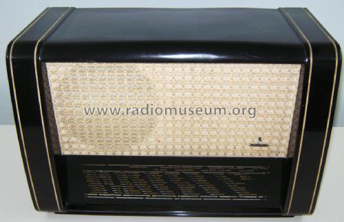
Siemens Spezial-Super 51GW Front1

Siemens Spezial-Super 51GW Front3

Siemens Spezial-Super 51GW Front4
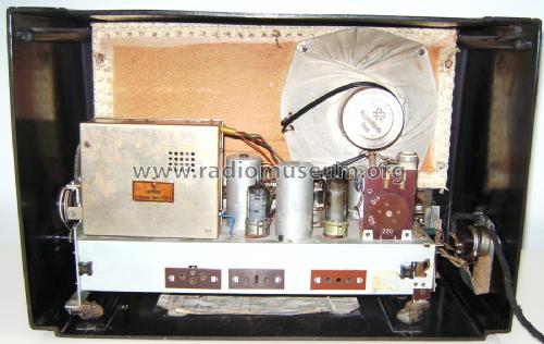
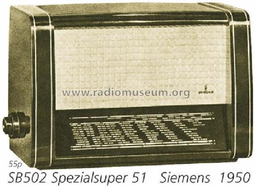
SB 502 GW

SB 502 GW

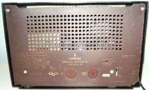
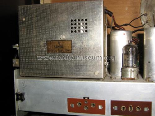
SB 502 GW Rückwand


Mit UKW-Tuner


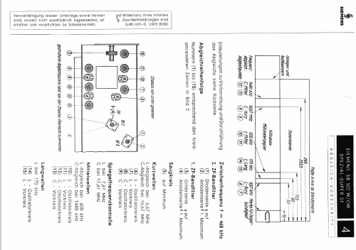
Orig. Werbefaltblatt 4-seitig
Klicken Sie auf den Schaltplanausschnitt, um diesen kostenlos als Dokument anzufordern.
- Anzahl Röhren
- 5
- Hauptprinzip
- Superhet allgemein; ZF/IF 468 kHz
- Anzahl Kreise
- 6 Kreis(e) AM
- Wellenbereiche
- UKW vorbereitet - hat Langwelle, Mittelwelle, Kurzwelle.
- Betriebsart / Volt
- Allstromgerät / 110, 125, 220 Volt
- Lautsprecher
- Dynamischer LS, keine Erregerspule (permanentdynamisch) / Ø 17 cm = 6.7 inch
- Material
- Bakelit (Pressstoff)
- von Radiomuseum.org
- Modell: Spezialsuper 51 SB502GW - Siemens & Halske, -Schuckert
- Form
- Tischgerät-gross, - Querformat (breiter als hoch oder quadratisch).
- Abmessungen (BHT)
- 550 x 300 x 220 mm / 21.7 x 11.8 x 8.7 inch
- Bemerkung
- Hergestellt im Berliner Werk. Vorbereitet für UKW-Einsatz U2GW (siehe dort).
- Nettogewicht
- 6.5 kg / 14 lb 5.1 oz (14.317 lb)
- Originalpreis
- 210.00 DM
- Datenherkunft
- Kat.d. Rundf.Gr.Handel 1950/51 / Radiokatalog Band 1, Ernst Erb
- Schaltungsnachweis
- Lange-Nowisch
- Bildnachweis
- Das Modell ist im «Radiokatalog» (Erb) abgebildet.
- Weitere Modelle
-
Hier finden Sie 2528 Modelle, davon 2135 mit Bildern und 1333 mit Schaltbildern.
Alle gelisteten Radios usw. von Siemens (& Halske, -Schuckert Werke SSW, Electrogeräte); Berlin, München
Sammlungen
Das Modell Spezialsuper 51 befindet sich in den Sammlungen folgender Mitglieder.
Forumsbeiträge zum Modell: Siemens & Halske, -: Spezialsuper 51 SB502GW
Threads: 2 | Posts: 15
Hello dear friends,
I have quite unusual problem with this apparatus.
Just to mention, I have quite experience with old radio restoration and reparation.
Problem with this radio at start was completely destroyed power supply section, do to previously reparation atempts.
It was all misconnected, but with diagram I downloaded from our Radiomusem site, it was quite easy to correct all misconnections, but!!! after I resoldered and checked all connections, after switching on, on referent point where it should be -9.1V, I measured -20V, and output tube anode start to glow, all other voltages were too low, and minus g1 was -3.6V (see picture). So I started to check again resistors and capacitors arrangement, replaced UL41, tried another output transformer etc..., but nothing happened, too much current flows, and quite simple problem is now headache....
Does anybody have an idea?
Thanks in advance, Peter.
Anlagen
- Shematics (165 KB)
Perica Adnadevic, 18.Jul.16
Replace 10nF capacitor between UAF42 anode and UL41 grid. It has too big leakage current
Tomasz Szczesniak, 18.Jul.16