Satellite Television System K1
Skyscan; Maidenhead
- Pays
- Royaume Uni
- Fabricant / Marque
- Skyscan; Maidenhead
- Année
- 1985–1991 ?
- Catégorie
- Récepteur TNT, internet ou satellite
- Radiomuseum.org ID
- 355372
- No. de transistors
- Semi-conducteurs présents
- Semi-conducteurs
- Principe général
- Super hétérodyne, conversion double ou triple
- Gammes d'ondes
- Bandes en notes
- Tension / type courant
- Alimentation Courant Alternatif (CA) / 230 Volt
- Haut-parleur
- - - Pas de sortie basse fréquence
- Matière
- Boitier métallique
- De Radiomuseum.org
- Modèle: Satellite Television System K1 - Skyscan; Maidenhead
- Forme
- Formes diverses décrites en notes
- Dimensions (LHP)
- 400 x 68 x 330 mm / 15.7 x 2.7 x 13 inch
- Remarques
-
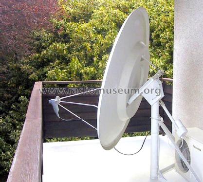
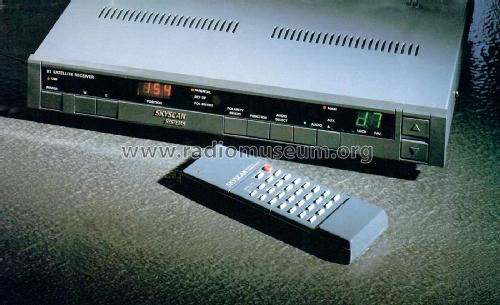
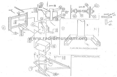
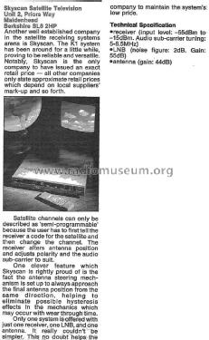
Direct-to-home (DTH) TV broadcasting began to take off in Europe during the mid 1980s. About 9000 K1 satellite television systems were marketed by Skyscan from 1985 to 1991. They comprised a polar mount with motorised actuator, an offset feed antenna dish with feedhorn and Ku band LNB, cables, and a satellite receiver with remote control.
Dish: Aluminised fibreglass 1.5 x 1.6m, 26˚ offset feed, Gain 44 dB. An optional 1.2m dish with 22˚ offset feed was also available.
Feedhorn: 10.95-11.75 GHz, VSWR 1.3, Scalar rings, WR75F flange RF port, Switchable linear polarisation with skew adjustment, remotely controlled by 3-wire sealed servo motor.
LNB: Input frequency range 10.95-11.7 GHz, Output frequency range 950-1700 MHz, Noise figure typ 2.0, max 2.3, Gain 55 ±3dB @ 10.95GHz, 57 ±3dB @ 11.7GHz, Flatness within 36MHz receiving channel ±0.5dB, Image rejection min 45dB, Output impedance 75Ω, DC supply 15-24V/200mA.
Actuator: Range 18", Mechanical limit switches. With a supply voltage of 36V the actuator draws 3A when moving a 500lb load.
Receiver: Type F input connector, Input frequency (first IF) 950-1750 MHz, Input level -55 to -15 dBm, 2nd IF 479.25 MHz, 3rd IF 70 MHz, Bandwidth 28 MHz, Internal analogue to digital conversion to signal metering microprocessor, True FM discriminator, Demodulator threshold better than 7dB, Composite baseband output 1V p/p, Video de-emphasis CCIR 625 lines, Video output level 1 Vp/p into 75 Ω, Phono jack output connector, Video response ±1dB 20 Hz to 5.25 MHz, Video SNR 50 dB @ carrier/noise 15 dB, AF response ±2dB 50 Hz-20 kHz, Audio de-emphasis 50 µs, Audio subcarrier main 6.6 MHz, aux 6.65 MHz, variable 5-8.5 MHz, Audio output 1V into 600 Ω phono jack, UHF output -70dBm, tuneable Ch 33-39, Pal I or Pal G, Parental control, 24V DC output for LNB, AC mains power requirement 20 W nominal. Three alkaline AA batteries for memory backup.
The dish was fabricated by a fibreglass boat builder in Kent, the LNB by MTI in Taiwan, and the receiver by AED Satellite Systems in Canada.
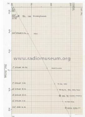
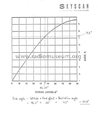
When the antenna mount is set up with the correct azimuth orientation, polar axis angle and declination offset for the latitude of the installation, the motorised actuator allows the dish to scan the geosynchronous satellite arc. The example chart shows the satellites that were received at Geneva, Switzerland, between 34˚ west and 24˚ east in September 1991.
- Prix de mise sur le marché
- 1,200.00 GBP
- Littérature
- - - Manufacturers Literature
- Schémathèque (1)
- -- Original prospect or advert (Electronics Today International Feb 1988, Page 16.)
- Auteur
- Modèle crée par Bruce Taylor. Voir les propositions de modification pour les contributeurs supplémentaires.
- D'autres Modèles
-
Vous pourrez trouver sous ce lien 1 modèles d'appareils, 1 avec des images et 0 avec des schémas.
Tous les appareils de Skyscan; Maidenhead
Collections
Le modèle Satellite Television System fait partie des collections des membres suivants.
