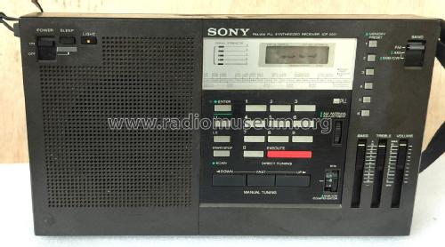
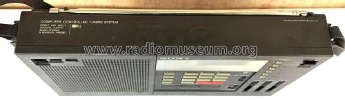
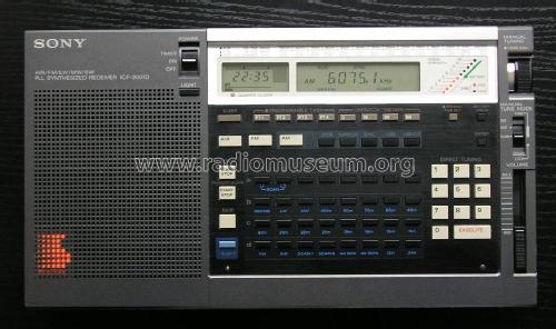
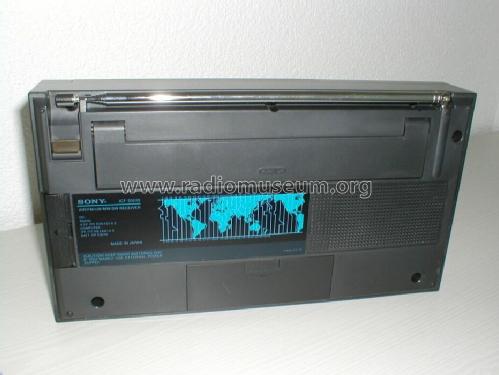
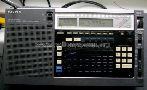
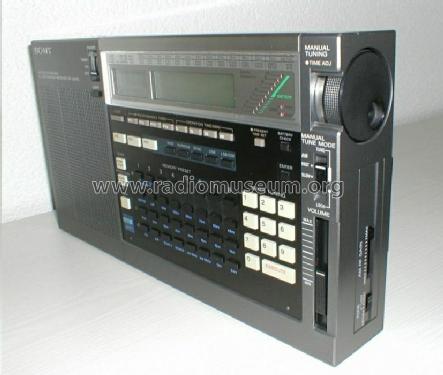
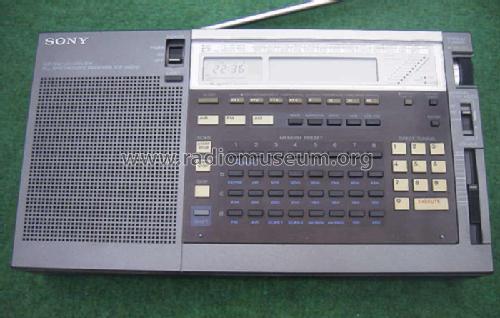
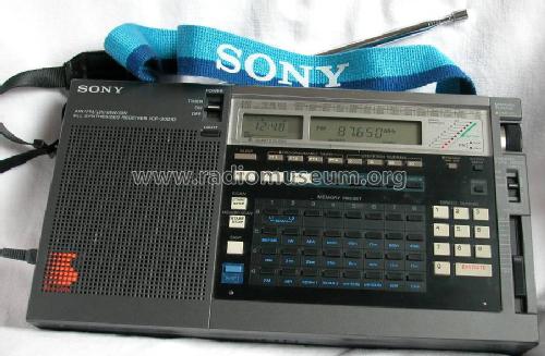
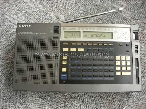
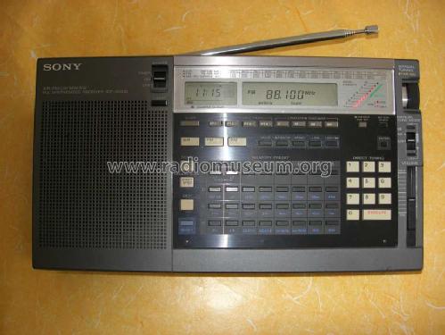
PLL Synthesized Receiver ICF-2001D
Sony Corporation; Tokyo
- País
- Japon
- Fabricante / Marca
- Sony Corporation; Tokyo
- Año
- 1985
- Categoría
- Radio - o Sintonizador pasado WW2
- Radiomuseum.org ID
- 74812


Internationale Version mit "AIR-Band"


SONY ICF-2001D


Variante ohne AIR - Band


Installation filtre KIWA (gris,grey color)

Mein treuer Reisebegleiter
Copyright by Rainer Jürgensen
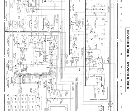
Haga clic en la miniatura esquemática para solicitarlo como documento gratuito.
- Numero de transistores
- 66
- Semiconductores
- 2SK193 2SB808 2SA1115 DTA124 2SK152 2SK439 2SK184 2SK192 2SK105 2SK212 2SC2839 2SC2786 2SC1623 2SA1162 2SB1013 2SC2785 2SD1020 DTC144 2SB810 µPD7503 µPC393 CX857 CX7961 LA1205 LB1411 LA4146 CD4001 CD4011 CD4013 CD4066 CD4069 CD4071 CD4081 CD4532 MC931 1S2835 1SS106 1SS168 1SS119 1SS148 1T26 1T33-08 TLUR122 SLP145B
- Principio principal
- PLL, Phase-locked loop; ZF/IF 19055/455 kHz
- Gama de ondas
- OM, OL, OC y FM
- Tensión de funcionamiento
- Pilas
- Altavoz
- Altavoz dinámico (de imán permanente) / Ø 9 cm = 3.5 inch
- Material
- Plástico moderno (Nunca bakelita o catalina)
- de Radiomuseum.org
- Modelo: PLL Synthesized Receiver ICF-2001D - Sony Corporation; Tokyo
- Forma
- Portátil > 20 cm (sin la necesidad de una red)
- Ancho, altura, profundidad
- 290 x 160 x 55 mm / 11.4 x 6.3 x 2.2 inch
- Anotaciones
-
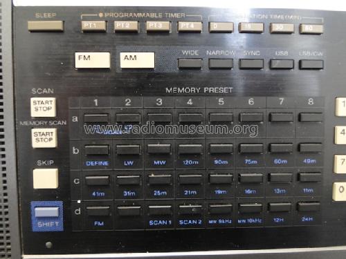
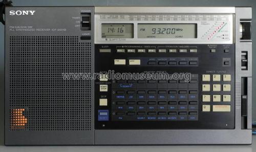
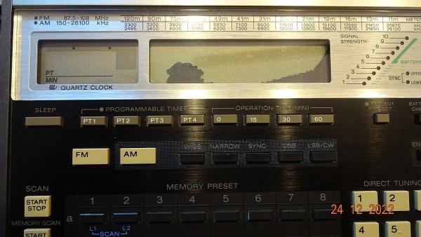
Sony ICF-2001D: Double conversion portable multiband radio, coverage 150 - 30000 kHz, FM 76 - 108 MHz, additional AIR band 116 - 136 MHz AM; AM, SSB (USB, LSB, ECSS-Sync), digital frequency readout, frequency keypad entry, 32 memories, clock.
Internationally, different variants were sold:
-
Version 1 (standard / international): frequency coverage 150 - 29999 kHz, 76 - 108 MHz and Air Band 116 - 136 MHz; SSB reception, external antenna jack
-
Version 2 (Germany / Deutschland FTZ): frequency coverage 150 - 26100 kHz, 87.5 - 108 MHz, no Air Band; SSB reception, external antenna jack
-
Version 3 (Italy ?): frequency coverage 150 - 285 and 530 - 26100 kHz, 87.5 - 108 MHz, no Air Band; no SSB reception or external antenna connector
On pictures, you can recognize the sets without Air band coverage, as they have only two white - grey push buttons AM / FM below the clock display, and not three.
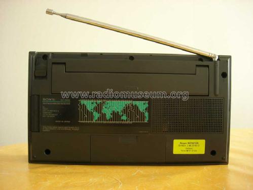
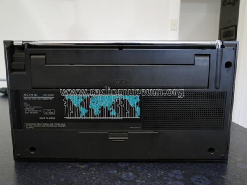
Radio part uses 3 x D cells (4.5V) but under them are 2 x AA cells for the Microprocessor/Clock/Memory (labelled "computer supply").
A rotary encoder tunes "fast or slow" or can be locked off. It's also used to increment and decrement the clock and multiple alarms. Each of the four alarms can have a duration (0, 15, 30, 60 minutes) and radio memory. The tape socket has a DC signal to initiate timer recordings.Matching power supply is Sony AC-140W (blue label, 4.5 V rated, different voltages)
Similar U.S. model is the Sony ICF-2010 with a slightly different power supply.
-
- Peso neto
- 1.7 kg / 3 lb 11.9 oz (3.744 lb)
- Precio durante el primer año
- 850.00 DM
- Ext. procedencia de los datos
- R. Lichte
- Mencionado en
- -- Original-techn. papers.
- Autor
- Modelo creado por Martin Bösch. Ver en "Modificar Ficha" los participantes posteriores.
- Otros modelos
-
Donde encontrará 4068 modelos, 3925 con imágenes y 975 con esquemas.
Ir al listado general de Sony Corporation; Tokyo
Colecciones
El modelo PLL Synthesized Receiver es parte de las colecciones de los siguientes miembros.
- Martin Bösch (CH)
- Hans Fischer (CH)
- Nikolai Galak (UA)
- Salvador Galan-Ocaña (E)
- Rudolf HEINZ (D)
- Peter ILIEF † 10.6.22 (CH)
- Daniel Jecker (F)
- Rainer Juergensen (D)
- Uday Kalburgi (IND)
- Eddie King (D)
- Wolfgang Lohrie (AUS)
- Antonio Marra (I)
- Jose Mesquita (P)
- Johann Nussbaum (D)
- Olivier Palix (F)
- Jacques-André Ramelet (CH)
- José Maria Santos-Sanchez (E)
- Heinz Schmidt (D)
- Patrice Schoser (F)
- Peter Seifert (D)
- Sándor Selyem-Tóth (H)
- Emile Stauber (CH)
- Michael Watterson (IRL)
Literatura
El modelo PLL Synthesized Receiver está documentado en la siguiente literatura.
Contribuciones en el Foro acerca de este modelo: Sony Corporation;: PLL Synthesized Receiver ICF-2001D
Hilos: 4 | Mensajes: 9
Hallo Radiofreunde
Habe heute mal meinen Sony ICF-2001D aus der Vitrine geholt dabei musste ich diesen Fehler am Display feststellen was ist das kann man das reparieren.
Grüsse und Frohe Weihnachten
Gerhard
Gerhard Härtl, 24.Dec.22
According to the Service Manual, the RF bands can be set differently. However, depending on the model type, specific hardware limitations are also implemented at the cabinet/keypad and on the electronic circuits, and these impede some RF band choices.

Location of the Diode Bridges on the KeyBoard PCB Assembly:
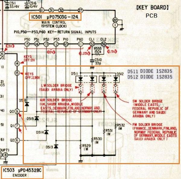
Jose Mesquita, 13.Sep.22
The original Service Manual (1985, 85C02129-1 9-951-647-11) lists the 2SK152-1 at several positions, namely Q302 LW/MW RF AMP and Q303 AM RF AMP.
However I found several versions of the Small PCB assembly (RF Input and I/O sockets, at least these ones exist:
- 1-614-277-12 and 1-614-277-13 (label at the copper trace side) - Older boards, older style "SMD" components.
- 1-614-277-15 (label at the oposite side of copper trace) - Later board, redesigned PCB copper traces, uses common SMD components at trace side.
At least on 1-614-277-15 PCB assemblies, both Q302 and Q303 uses the 2SK152-2 installed from factory.
The 2SK152-1 and 2SK152-2 have different specifications, namely IDSS operating current. Therefore the reference voltage points at Dreno and Source of these 2SK152-1 JFETs listed in the Service Manual may not apply entirely to the 2SK152-2. I observed large variations, especially on the Q302, despite the radio being operating very well. That said, those reference voltages are still useful as a starting point for troubleshooting.
Jose Mesquita, 12.Sep.22
Hallo, liebes Forum!
Bei meinem ICF-2001D besteht das Problem, dass der Schieberegler für die Lautstärke mittlerweile stark kracht. Selbiges Problem habe ich auch beim kleinen Bruder ICF-7600D. Gibt es eine Möglichkeit, diesen nachhaltig zu restaurieren (also nicht Kontaktspray 'reinknallen)? Falls nicht: Kann man diesen Regler heute noch kaufen?
Über eine Info würde ich mich freuen!
Viele Grüße,
Torsten, DL8KFO
Torsten Blens, 30.Apr.20