- Land
- Australien
- Hersteller / Marke
- Standard Telephones and Cables Pty, Ltd (STC), Sydney
- Jahr
- 1936
- Kategorie
- Rundfunkempfänger (Radio - oder Tuner nach WW2)
- Radiomuseum.org ID
- 169747
Klicken Sie auf den Schaltplanausschnitt, um diesen kostenlos als Dokument anzufordern.
- Anzahl Röhren
- 5
- Hauptprinzip
- Super mit HF-Vorstufe; ZF/IF 175 kHz; 2 NF-Stufe(n)
- Anzahl Kreise
- 7 Kreis(e) AM
- Wellenbereiche
- Mittelwelle, keine anderen.
- Betriebsart / Volt
- Akku und/oder Batterie / 135 & 2 Volt
- Lautsprecher
- Dynamischer LS, keine Erregerspule (permanentdynamisch) / Ø 8 inch = 20.3 cm
- Material
- Gerät mit Holzgehäuse
- von Radiomuseum.org
- Modell: 510B Ch= 51B - Standard Telephones and Cables
- Form
- Standgerät auf niedrigen Beinen (Beine < 50 % der Gesamthöhe).
- Bemerkung
-
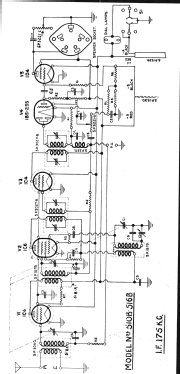
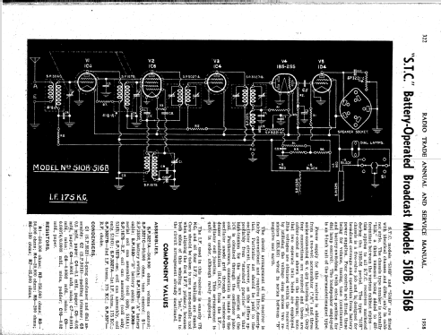
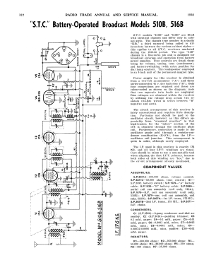
S.T.C. models "510B" and "516B" are fitted with identical chasses and differ only in cabinet style. The chassis type number is actually "51B," a third numeral being added to differentiate between the various cabinet styles this applies to all S.T.C. receivers marketed during the 1935-36 period. The type "51B” chassis is a five-valve job and is designed for broadcast coverage and operation from battery power supplies. Four controls are fitted, these being for volume, tuning, tone (continuous), and battery-switching (with an extra position for dial lamp control).
The loudspeaker employed is an 8-inch unit of the permanent magnet type.The power supply for this receiver is obtained from a two-volt accumulator ("A") and three series-connected 45 v. dry batteries ("B"). Only four connections are required and these are colour coded as shown on the diagram; note that two separate twin leads are employed.
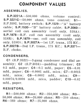
Bias voltages are obtained within the receiver by utilising the voltage drop across two resistors (R5, R6) wired in series between "B" negative and earth.
The circuit arrangement of this receiver is fairly conventional and requires little description.
Particular notice should be paid to the oscillator circuit, however, as this differs appreciably from "standard practice" in that high tension for the "mixer" section of the 1C6 is obtained through the oscillator plate coil. Furthermore, the connection is made to the oscillator anode grid through a resistor-condenser combination (R4, C4), from the IF oscillator coil junction. This arrangement is quite in order, although rarely employed.
The IF used in this receiver is exactly 175 KC. and all four IFT windings are tuned.
Care should be taken to use a non-metallic tool when aligning the first IFT primary, because both sides of this winding are "hot," due to the circuit arrangement already mentioned.
Radio Trade Annual 1939, Page 322.
- Originalpreis
- 29.00 Aus£
- Literatur/Schema (1)
- Radio Trade Annual 1938 P322.
- Autor
- Modellseite von Stuart Irwin angelegt. Siehe bei "Änderungsvorschlag" für weitere Mitarbeit.
- Weitere Modelle
-
Hier finden Sie 616 Modelle, davon 273 mit Bildern und 306 mit Schaltbildern.
Alle gelisteten Radios usw. von Standard Telephones and Cables Pty, Ltd (STC), Sydney