- Paese
- Australia
- Produttore / Marca
- Standard Telephones and Cables Pty, Ltd (STC), Sydney
- Anno
- 1936
- Categoria
- Radio (o sintonizzatore del dopoguerra WW2)
- Radiomuseum.org ID
- 335137
Clicca sulla miniatura dello schema per richiederlo come documento gratuito.
- Numero di tubi
- 5
- Principio generale
- Supereterodina (in generale); ZF/IF 450 kHz; 2 Stadi BF
- N. di circuiti accordati
- 6 Circuiti Mod. Amp. (AM)
- Gamme d'onda
- Solo onde medie (OM).
- Tensioni di funzionamento
- Alimentazione a corrente alternata (CA) / 200; 250 Volt
- Altoparlante
- AP elettrodinamico (bobina mobile e bobina di eccitazione/di campo)
- Materiali
- Mobile in legno
- Radiomuseum.org
- Modello: 514A Ch= 51A - Standard Telephones and Cables
- Forma
- Soprammobile con qualsiasi forma (non saputo).
- Annotazioni
-
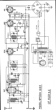
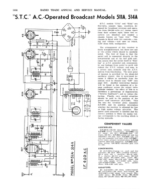
STC Models 511A & 514A are 5-valve Console type receivers designed for braoadcast coverage and operation from 200-250 volts AC mains.
Apart from the cabinet style, these two receivers are identical & employ a chassis known as type “51A”. This chassis is fitted with two controls, tuning & volume & uses an 8-inch, 2,500Ω field, loudspeaker.
The arrangement of this receiver is fairly straightforward, but there are one or two points that should be carefully noted. The first of these is that the aerial coil is connected directly to the low-potential end of the 6A7 grid coil; this means that the aerial itself is “floating” at AVC potential & consequentially, any leakage from aerial to earth will reduce the AVC & may in a severe case actually stop the AVC system functioning.
The next point of interest is provided by a shunt-fed oscillator circuit; this is mentioned because it differs so markedly from the system used in chassis type “51B”.
Another interesting feature will be found in the omission of a by-pass condenser across the output valve cathode resistor; the effect of this is to introduce a percentage of degeneration {“inverse feedback”) & so reduce distortion. Finally, very important attention should be paid to the position of the power cord connector (SP 3106). This fits into the terminal plate assembly (SP 3097) & its position determines whether the receiver is adjusted for low or high mains voltage operation.
The power cord connector is labeled, and the correct position is when the mains voltage corresponds to the marking facing upwards.
Radio Trade Annual 1939, Page 323.
- Letteratura / Schemi (1)
- Radio Trade Annual of Australia (6th Edition 1938.)
- Letteratura / Schemi (2)
- Mingay's "Radio Diagram & I.F. Index
- Autore
- Modello inviato da Martin Kent. Utilizzare "Proponi modifica" per inviare ulteriori dati.
- Altri modelli
-
In questo link sono elencati 616 modelli, di cui 272 con immagini e 305 con schemi.
Elenco delle radio e altri apparecchi della Standard Telephones and Cables Pty, Ltd (STC), Sydney