- Country
- Australia
- Manufacturer / Brand
- Standard Telephones and Cables Pty, Ltd (STC), Sydney
- Year
- 1936
- Category
- Broadcast Receiver - or past WW2 Tuner
- Radiomuseum.org ID
- 170949

Click on the schematic thumbnail to request the schematic as a free document.
- Number of Tubes
- 6
- Number of Transistors
- Semiconductors
- W4_Westector
- Main principle
- Superhet with RF-stage; ZF/IF 170/175 kHz; 3 AF stage(s)
- Tuned circuits
- 7 AM circuit(s)
- Wave bands
- Broadcast only (MW).
- Power type and voltage
- Storage and/or dry batteries / 135 & 6 & -9 Volt
- Loudspeaker
- Permanent Magnet Dynamic (PDyn) Loudspeaker (moving coil) / Ø 8 inch = 20.3 cm
- Material
- Wooden case
- from Radiomuseum.org
- Model: 686B Ch= 68B - Standard Telephones and Cables
- Shape
- Console, Lowboy (legs < 50 %).
- Notes
-
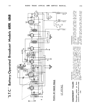
STC Model 680B & 686B are six-valve receivers designed for broadcast coverage and operation from battery power supplies. These receivers ate identical except for their cabinet style (which is of the console-style in each case) & employee chassis type “68B”. The chassis is fitted with four controls, volume, tuning, battery switch (two circuits), and dial light switch. An 8-inch permanent magnet loudspeaker is used in each case.
Power supply for these receivers is obtained from a 6-volt accumulator (“A”), three series-connected 45 v dry batteries (“B”), and a 9-v dray battery (“C”).
Separate cables are used for connection to each of these batteries & these are colour-coded as shown on the diagram.It should be noted the bias battery only provides grid voltage for the two type 30 AF amplifiers, bias for the type 19 being obtained from the drop across the remaining two-volt valve filaments (all of which are connected in parallel) & the series resistor R7. The 6A7 & the two type 34 valves are operated at zero bias under “no signal” conditions.
The design of the receiver is rather unusual from two aspects.
First, the use of a 6-volt heater valve as a frequency converter, and second the use of a “Westector” dry rectifier (D1) as a half-wave diode detector and AVC rectifier. The last, of course, results in a saving of one valve and its associated filament drain.
A further point of interest lies in the use of an oscillator system similar to that employed in chassis type “51B”, in which the mixer section of the frequency converter receives its plate voltage through the oscillator coil. Finally, the series-parallel filament network and grid returns should be studied carefully before attempting service operations.
Radio Trade Annual 1938, Page 329.
- Literature/Schematics (1)
- Radio Trade Annual 1938 P328.
- Author
- Model page created by Stuart Irwin. See "Data change" for further contributors.
- Other Models
-
Here you find 616 models, 273 with images and 306 with schematics for wireless sets etc. In French: TSF for Télégraphie sans fil.
All listed radios etc. from Standard Telephones and Cables Pty, Ltd (STC), Sydney