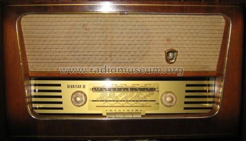
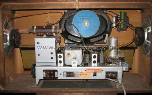
Sekretär III 697/75GWU 3D
Stern-Radio Sonneberg, VEB, RFT; SONRA; -vorm.: EAK (Ostd.) - ex. AEG
- Hersteller / Marke
- Stern-Radio Sonneberg, VEB, RFT; SONRA; -vorm.: EAK (Ostd.) - ex. AEG
- Jahr
- 1960 ??
- Kategorie
- Rundfunkempfänger (Radio - oder Tuner nach WW2)
- Radiomuseum.org ID
- 126147
- Anzahl Röhren
- 6
- Anzahl Transistoren
- Halbleiter
- Tr.Gl.=Metal-rectif.
- Hauptprinzip
- Superhet allgemein; ZF/IF 473/10700 kHz
- Anzahl Kreise
- 6 Kreis(e) AM 9 Kreis(e) FM
- Wellenbereiche
- Langwelle, Mittelwelle und UKW (FM).
- Betriebsart / Volt
- Allstromgerät / 220 Volt
- Lautsprecher
- 3 Lautsprecher / Ø 22 cm = 8.7 inch
- Belastbarkeit / Leistung
- 2 W (Qualität unbekannt)
- Material
- Gerät mit Holzgehäuse
Die GFGF Zeitschrift Funkgeschichte bringt interessante Artikel zu Radios, Funkwesen und Medien. Bei Radiomuseum.org finden Sie die vollständigen Hefte früherer Ausgaben als PDF zum Download.
- von Radiomuseum.org
- Modell: Sekretär III 697/75GWU 3D - Stern-Radio Sonneberg, VEB,
- Form
- Tischmodell, Zusatz nicht bekannt - allgemein.
- Abmessungen (BHT)
- 560 x 315 x 185 mm / 22 x 12.4 x 7.3 inch
- Bemerkung
- TA nur mit Trenntrafo möglich.
- Nettogewicht
- 7 kg / 15 lb 6.7 oz (15.419 lb)
- Datenherkunft
- - - Data from my own collection
- Autor
- Modellseite von Klemens Rhode angelegt. Siehe bei "Änderungsvorschlag" für weitere Mitarbeit.
- Weitere Modelle
-
Hier finden Sie 385 Modelle, davon 312 mit Bildern und 288 mit Schaltbildern.
Alle gelisteten Radios usw. von Stern-Radio Sonneberg, VEB, RFT; SONRA; -vorm.: EAK (Ostd.) - ex. AEG
Sammlungen
Das Modell Sekretär III befindet sich in den Sammlungen folgender Mitglieder.
Forumsbeiträge zum Modell: Stern-Radio: Sekretär III 697/75GWU 3D
Threads: 1 | Posts: 3
I'm restoring a Sekretär III 697/75GWU 3D radio. There wasn't a schematic for this model in RMorg but I used a schematic for model Sekretär III 697/62GWU which I believe to be close enough. There are no component values in the schematic and I need to know the value of one resistor. It is burned open and the markings are no longer visible. I think it is R11 in the schematic (in the lower left corner, antenna circuit). I have no idea how it got burned. There is no visible damage in the other components.
Also I removed the 50 + 100 uF electrolytic capacitor can but I forgot to look which one is the first and which one is the second filter. I'm guessing that the 100 uF is the first. Am I right?
The final question is about the half wave selenium rectifier. I measured its resistance with a digital ohm meter and I got 1.3 megaohms in the other direction and 1.6 megaohms in the other. I assume that it is bad?
All answers will be greatly appreciated.
Timo
Timo Haveri, 16.Jun.08


