31 (Ch= 41)
Superla - Cresa; Modena, Bologna
- Country
- Italy
- Manufacturer / Brand
- Superla - Cresa; Modena, Bologna
- Year
- 1934
- Category
- Broadcast Receiver - or past WW2 Tuner
- Radiomuseum.org ID
- 165953
-
- alternative name: Cresa Radio; Modena
Click on the schematic thumbnail to request the schematic as a free document.
- Number of Tubes
- 4
- Main principle
- Superheterodyne (common); ZF/IF 450 kHz; Reflex
- Wave bands
- Broadcast only (MW).
- Power type and voltage
- Alternating Current supply (AC) / 115; 130; 145; 160 220 Volt
- Loudspeaker
- Electro Magnetic Dynamic LS (moving-coil with field excitation coil) / Ø 16 cm = 6.3 inch
- Power out
- 2 W (unknown quality)
- Material
- Wooden case
- from Radiomuseum.org
- Model: 31 - Superla - Cresa; Modena,
- Shape
- Tablemodel, high profile (upright - NOT Cathedral nor decorative).
- Dimensions (WHD)
- 330 x 400 x 240 mm / 13 x 15.7 x 9.4 inch
- Notes
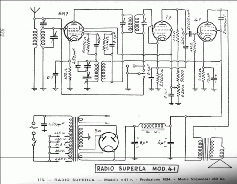
- Sono noti alcuni modelli che utilizzano lo schema indicato come mod. 41, ma con targhetta identificativa che riporta "Modello 31".
Esiste uno schema di Superla mod. 31 a sole tre valvole (si veda Superla 31).
- Net weight (2.2 lb = 1 kg)
- 7 kg / 15 lb 6.7 oz (15.419 lb)
- Mentioned in
- Antique Radio Magazine - Italy, Club Antique Radio Magazine (n. 104, Nov.-Dec. 2011)
- Literature/Schematics (1)
- -- Schematic (D.E. Ravalico, Il Radio libro, III ed., Hoepli)
- Author
- Model page created by Enrico Puccini. See "Data change" for further contributors.
- Other Models
-
Here you find 119 models, 67 with images and 56 with schematics for wireless sets etc. In French: TSF for Télégraphie sans fil.
All listed radios etc. from Superla - Cresa; Modena, Bologna
Forum contributions about this model: Superla - Cresa;: 31
Threads: 1 | Posts: 2
Vorrei sottoporre questo quesito agli iscritti di radiomuseum.
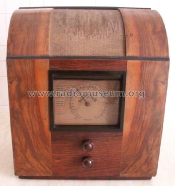
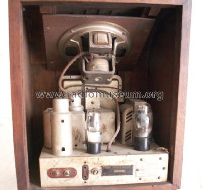
Appartiene alla mia collezione una radio Superla che riporta nella targhetta originale mod. 31 n. 15311 e monta n. 4 valvole 6A7, 77, 41, 80.
Dallo Schemario Ravalico ed. 1944 lo schema elettrico del mod. 31 risulta con tre valvole 7F7, 42, 80 mentre lo schema del mod. 41 riporta le valvole montate sulla radio che ho fisicamente.
La foto riportata su Antique radio vol.III pag. 249 relativa al mod. 31 è completamente diversa dalla mia.
La targhetta applicata alla radio è rivettata originale e non manomessa è come se la Superla avesse applicato una targhetta errata.
Vorrei inserire questo modello ma non saprei in che modo, direi a questo punto 41.
Chiedo se qualcuno ha documentazione che possa spiegare questa anomalia.
Allego foto:
Saluti
E. Puccinni
Attachments
- Superla (95 KB)
- Superla interno (120 KB)
- Superla targhetta (105 KB)
Enrico Puccini, 28.Nov.09