RMSV-Meter TE-65
Tech Instruments Co. Ltd.; Tokyo
- Country
- Japan
- Manufacturer / Brand
- Tech Instruments Co. Ltd.; Tokyo
- Year
- 1970–1972 ??
- Category
- Service- or Lab Equipment
- Radiomuseum.org ID
- 99728


Gerätebeschreibung

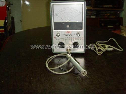
TECH Vacuum Tube Voltmeter TE-65

Click on the schematic thumbnail to request the schematic as a free document.
- Number of Tubes
- 2
- Wave bands
- - without
- Power type and voltage
- Alternating Current supply (AC) / 220-240 Volt
- Loudspeaker
- - - No sound reproduction output.
- Material
- Metal case
- from Radiomuseum.org
- Model: RMSV-Meter TE-65 - Tech Instruments Co. Ltd.;
- Shape
- Tablemodel, high profile (upright - NOT Cathedral nor decorative).
- Dimensions (WHD)
- 140 x 215 x 150 mm / 5.5 x 8.5 x 5.9 inch
- Notes
-
- Technische Daten:
- Innenwiderstand
- 11MΩ auf allen Bereichen
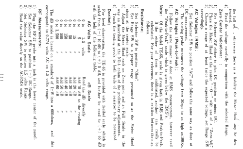
- Gleichspannungsmeßbereiche
- 1,5/5/15/50/150/500/1500V
- Wechselspannungsmeßbereiche
- Veff: 1,5/5/15/50/150/500/1500V
- Vss: 1,4/4/14/40/140/400/1400/4000V
- Widerstandsmeßbereiche
- 10/100/1k/10k/1M/10MΩ
- dB:
- -10 bis +65dB (0dB=1mW an 600Ω)
- Innenwiderstand
- Normalzubehör
- Gleichspannungsprüfspitze
- 2 Meßleitungen
- 1 Monozelle 1,5V
- 1 Bedienungsanleitung
- Sonderzubehör
- HV-Prüfspitze 30kV (28,50 DM)
- HF-Tastkopf 250MHz (26 DM)
Ähnlich oder baugleich mit Conrad CTR Röhrenvoltmeter HRV-240
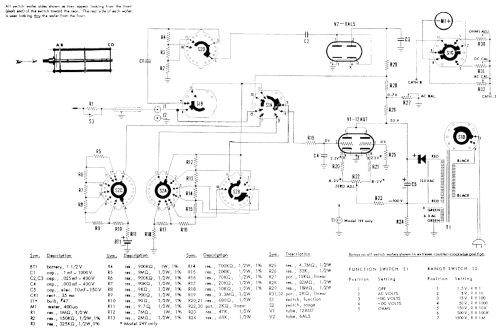
The Eico 232 peak to peak VTVM seems to be an identical design supplied as a kit, thus had a detailed schematic.
Rated for up to 60 MHz without a special probe.
- Technische Daten:
- Net weight (2.2 lb = 1 kg)
- 2.5 kg / 5 lb 8.1 oz (5.507 lb)
- Price in first year of sale
- 178.50 DM
- Literature/Schematics (1)
- -- Original-techn. papers. (Technik-Versand KG, Katalog Nr. 23, 1972)
- Author
- Model page created by Jos Lauth. See "Data change" for further contributors.
- Other Models
-
Here you find 18 models, 17 with images and 9 with schematics for wireless sets etc. In French: TSF for Télégraphie sans fil.
All listed radios etc. from Tech Instruments Co. Ltd.; Tokyo
Collections
The model RMSV-Meter is part of the collections of the following members.
Forum contributions about this model: Tech Instruments Co.: RMSV-Meter TE-65
Threads: 1 | Posts: 4
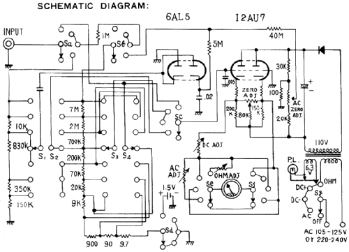
I noticed that the Ohms range was erratic. Many or most of the schematics don't show it, but the 1.5V nominal D Cell (mono cell) is actually only connected when the left switch is at ohms.
Also the battery will run down quickly if there is a short on the probe leads on the low ohms range and on Ohms.
The resistance in series with the battery to test lead is low on low ranges:
9.7
90 + 9.7
900 + 90 + 9.7
9K + 900 + 90 + 9.7
Etc.
So if a voltage is on the test input then there can be considerable input current if the left switch is at Ohms (battery connected).
Naturally the 9.7, 90 and 900 resistors were a bit cooked. The 9.7 seems to have been 12 Ohms, it read 4 Ohms. Perhaps it had a parallel resistor. The 90 and 900 were both pairs of resistors.
So on the lowest range the battery supplies between 110mA and 160mA depend on if near exhausted or new. Obviously the other ranges progressively use about 1/10th each time.
As the valves take 600mA and the 6.3V winding is earthed at one side, it might be feasible to use a 1.25V to 1.6V regulator based on an LM317 (minimum is 1.2V approx.). However that would be easily damaged on the low resistance ranges by an in circuit voltage.
Perhaps the safer approach is simply to add a 250mA fuse to protect the resistors and battery on the low resistance ranges. An LM317 could have a reverse rectifier across it, but unlike a battery which can sink current long enough for the fuse to blow, there is nothing to sink current from the external source to blow the fuse.
Michael Watterson, 07.Jun.24