- Hersteller / Marke
- Telefunken Deutschland (TFK), (Gesellschaft für drahtlose Telegraphie Telefunken mbH
- Jahr
- 1955/1956
- Kategorie
- Rundfunkempfänger (Radio - oder Tuner nach WW2)
- Radiomuseum.org ID
- 135007


US model has full FM coverage (88-108 MHz)


Klicken Sie auf den Schaltplanausschnitt, um diesen kostenlos als Dokument anzufordern.
- Anzahl Röhren
- 7
- Hauptprinzip
- Superhet allgemein; ZF/IF 460/10700 kHz; Exportmodell
- Anzahl Kreise
- 7 Kreis(e) AM 11 Kreis(e) FM
- Wellenbereiche
- Mittelwelle, Kurzwelle und UKW (FM).
- Betriebsart / Volt
- Netz- / Batteriespeisung / AC 110; 125; 150; 220 / 1.5 & 90 Volt
- Lautsprecher
- Dynamischer (permanent) Ovallautsprecher
- Material
- Diverses Material
- von Radiomuseum.org
- Modell: Elite - Telefunken Deutschland TFK,
- Form
- Reisegerät > 20 cm (netzunabhängig betreibbar)
- Abmessungen (BHT)
- 380 x 270 x 150 mm / 15 x 10.6 x 5.9 inch
- Bemerkung
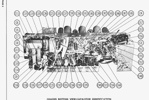
- The Telefunken model "Elite" is an export version of Telefunken Bajazzo, imported and distributed in the USA by American Elite, Inc., 7 Park Ave., New York, NY. It therefore has broadcast band, two SW and FM instead of LW, broadcast, SW and FM. It uses a Nickel-cadmium storage battery. Be careful and take it away because they often leak after such long time. Photofact shows on the title page the possible voltages but in the part list it shows a transformer for 117 volts primary. The speaker is 4" x 6" in diameter.
- Nettogewicht
- 7.5 kg / 16 lb 8.3 oz (16.52 lb)
- Literatur/Schema (1)
- Photofact Folder, Howard W. SAMS (Date 1-57, Set 343, Folder 11)
- Autor
- Modellseite von Ernst Erb angelegt. Siehe bei "Änderungsvorschlag" für weitere Mitarbeit.
- Weitere Modelle
-
Hier finden Sie 3582 Modelle, davon 3170 mit Bildern und 2126 mit Schaltbildern.
Alle gelisteten Radios usw. von Telefunken Deutschland (TFK), (Gesellschaft für drahtlose Telegraphie Telefunken mbH
Sammlungen
Das Modell Elite befindet sich in den Sammlungen folgender Mitglieder.
Forumsbeiträge zum Modell: Telefunken: Elite
Threads: 1 | Posts: 1
Fellow Radiophiles,
I found an error in the Sams Photofact FM IF alignment instructions for the Telefunken Elite.
The error is in the instructions at step 18:
![]()
This step is under the IF instructions, but it is not an IF adjustment. It should be done as the first step of the FM front end alignment.
The purpose of this step is to balance the front end mixing bridge to minimize antenna radiation of the Local FM oscillation produced by the DC90.
The adjustment is done with an insulated tool at the trimmer capacitor marked by A24. The following excerpt is from the Photofact instructions and is correct.

The measurement is done with an VHF RF voltmeter at the FM antenna terminals, or with an oscilloscope with >100MHz bandwidth and mV sensitivity.
Turn A24 to minimize the presence of local oscillator frequency at the antenna, with the dial set to 98MHz. The local oscillator will be running at 98MHz+10.7MHz=108.7MHz.
For comparision with correct instructions, the following excerpts show the equivalent trim for the Telefunken Bajazzo 55, which has a very similar chassis. The trim is done at C under similar conditions, with the dial centered at 94MHz.

I made the adjustment with a Tektronix 7854 oscilloscope and 7A26 vertical plug-in. I coupled the 240 Ohm FM antenna with a ballun transformer to step down to 60 Ohms, and terminated the 2 foot 50 Ohm coax cable with 50 Ohms at the scope. The Local oscillator leakage seen at the scope varied from an optimum of 10mVp-p, to 200mVp-p when the trimmer was rotated for worst leakage.
The exact impedance and termination for this measurement are not important. I gave them here to support the circumstances of the voltage measurements. The important thing is to minimize the radiated oscillation. You will also notice that the leakge is not constant throught the dial, and this is the reason why the 98MHz center frequency is chosen for the adjustment.
Regards,
-Joe
Joe Sousa, 30.Apr.10