Lampemètre (Röhrenprüfgerät) L39
Télémesure, Radio-Comptoir du Sud-Est - voir aussi MARER; Lyon
- Country
- France
- Manufacturer / Brand
- Télémesure, Radio-Comptoir du Sud-Est - voir aussi MARER; Lyon
- Year
- 1939
- Category
- Service- or Lab Equipment
- Radiomuseum.org ID
- 272870

Click on the schematic thumbnail to request the schematic as a free document.
- Wave bands
- - without
- Power type and voltage
- Alternating Current supply (AC) / 110; 130; 150; 220 Volt
- Loudspeaker
- - - No sound reproduction output.
- Material
- Leather / canvas / plastic - over other material
- from Radiomuseum.org
- Model: Lampemètre L39 - Télémesure, Radio-Comptoir du
- Shape
- Tablemodel, slant panel.
- Dimensions (WHD)
- 375 x 150 x 270 mm / 14.8 x 5.9 x 10.6 inch
- Notes
-
This Télémesure model L39 is proposed on the basis of a device, without any type identification. However, it is very similar to models with type designation L39.
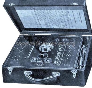
Lectern model in wooden suitcase, covered with black leatherette. The tester can be used for emission tests.
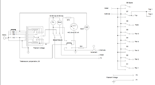
A position switch for the filament current is located below the meter (scale 0-50 mA). Positions: 2, 2.5, 4, 5, 6.3, 7.5, 10, 13, 16, 20, 25 and 30 volts.
A switch with the text "Essai/Mesure" is situated on the left of the position switch. In the upper position, the filament can be tested, a measurement can be performed with the switch in the lower position.
To the right of the position switch is a push-button, that can be used to insulate the filament from the cathode.
Right below the position switch, test leads and a jumper can be used. The two upper contacts, labeled "L", can be used for a continuity test.The jumper in the middle is an interconnection for the test voltage. This connection can also be used to insert 70 volts DC for measuring capacitors. The two lower contacts, labeled "M", can be used for testing a capacitor. The neon tube serves as an indicator.
The contacts for the filaments are hardwired; the switches, numbered 1 to 8, can be used to convert a measurement voltage of 110 volts on one of the other tube pins. Because the tube tester is only suitable for pre-war tubes with a maximum of 8 pins, only the first 6 switches are used. Switch 7 switches the top connection (orange and black bus) and the central pivot of a loctal tube. Switch 8 can be used in case of an extension.
On the left and right there are two strips with tube sockets, numbered from 1 to 9 (left: 1-4, 5-9 on the right), numbered from bottom to top. Another row of tube sockets is situated at the top. The left base could be used as extra.
Right of the left tube strip are two indicators: green: filament ok, red: short circuit.
On the right of the indicator lamps is a neon lamp with a printed scale (1-10). It serves as an indicator tube for a capacitor test.
Warning: when the tube tester is connected to the mains, high voltages can be present on the metal housing or the metal paint of the test tube and on the metal base of a loctal tube!
- Net weight (2.2 lb = 1 kg)
- 3.6 kg / 7 lb 14.9 oz (7.93 lb)
- Author
- Model page created by John Koster. See "Data change" for further contributors.
- Other Models
-
Here you find 10 models, 9 with images and 1 with schematics for wireless sets etc. In French: TSF for Télégraphie sans fil.
All listed radios etc. from Télémesure, Radio-Comptoir du Sud-Est - voir aussi MARER; Lyon
Collections
The model Lampemètre (Röhrenprüfgerät) is part of the collections of the following members.