The Tingey Unit System
Tingey Wireless, W.R.H. Tingey; London
- Country
- Great Britain (UK)
- Manufacturer / Brand
- Tingey Wireless, W.R.H. Tingey; London
- Year
- 1922
- Category
- Amateur-Receiver (amateur bands, may include broadcast bands)
- Radiomuseum.org ID
- 330529
- Number of Tubes
- 0
- Valves / Tubes
- R_England
- Main principle
- TRF (Tuned-Radio-Frequency but use of regeneration unknown)
- Wave bands
- Broadcast (MW) and Long Wave.
- Power type and voltage
- Storage and/or dry batteries
- Loudspeaker
- - For headphones or amp.
- Material
- Wooden case, TUBES VISIBLE.
- from Radiomuseum.org
- Model: The Tingey Unit System - Tingey Wireless, W.R.H. Tingey
- Shape
- Tablemodel, with any shape - general.
- Notes
-
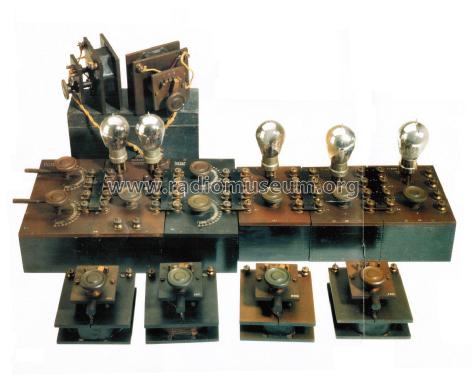
The Tingey Unit System is a modular receiver system for licenced amateurs interested in experimenting with wireless transmissions. The system can be used with different inductances to cover from 200 to 24,000 meters (see below).
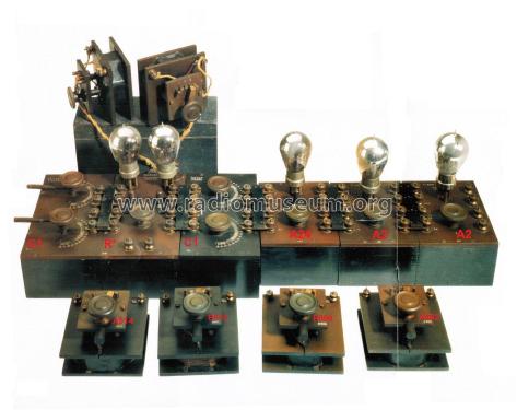
A possible combination of units is C1 (tuner), R1 (receiver) with one of I1 coils, A1 (RF amp), any combination of A2 (RF amp) and A3 (AF amp) units and a T1 headset transformer. There was also a Crystal Rectifier Unit, a detector especially recommended for telephony, which could replace a valve detector.
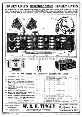
The following units were available in January 1922:
- A1 Multi HF Amplifier Transformer Unit: RF amp to be used with transformers T2 (1 valve)
- A2 Multi HF Amplifier Unit: RF amp, choke and resistance type (1 valve)
- A3 Multi LF Amplifier Unit: AF amp (1 valve)
- A4 Multi HF Unit: without inductance or variable condenser
- C1 Condensers: a pair of variable capacitors, tuning for R1
- I1 Type A Inductance: coils from 200 to 1,600 meters
- I1 Type B Inductance: coils from 1,000 to 8,500 meters
- I1 Type C Inductance: coils from 5,000 to 24,000 meters
- J1 to J8 Junction brackets: connector brackets with 2 or 4 leads
- P1 Inductance Plugs: different plugs to connect the coils I1
- P2 Brown's Phones: S.G. Brown type D headphones
- R1 Receivers: a receiver, needs tuner C1 (2 valves)
- R6: Type R valves
- T1 Multi Telephone Transformer Unit: to connect headphones
- T2 Interchangeable Transformers: to be used with A1
In Aug. 1922 additional units were added:
- A24 Combined Unit: both fixed and variable tuning, tuned or stand-by position
- R* Receiver: for Type R valves
- R1* Receivers: for Mullard valves
- RS Single Valve Receiver
- RV Unit HF: to follow RS unit
Tingey also offered Brown's Relay Unit for rapid connection to the Unit System (probably this model).
Similar sets were offered by:
- Marconi Scientific Instrument (UK), see e.g. this unit
- Peto-Scott (UK), see units listed here
- Bonnefont (F), see Radio-Monteurs
- Brunet (F), see Radio-Bloc
- Radio L.L. (F), see Audionette
- Mentioned in
- Archeofon rivista Italiana per mostra radio d'epoca
- Literature/Schematics (1)
- -- Original prospect or advert (WW and Radio Review, Jan. 1, 1922)
- Author
- Model page created by Pier Antonio Aluffi. See "Data change" for further contributors.
- Other Models
-
Here you find 15 models, 14 with images and 0 with schematics for wireless sets etc. In French: TSF for Télégraphie sans fil.
All listed radios etc. from Tingey Wireless, W.R.H. Tingey; London


