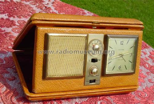
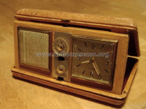
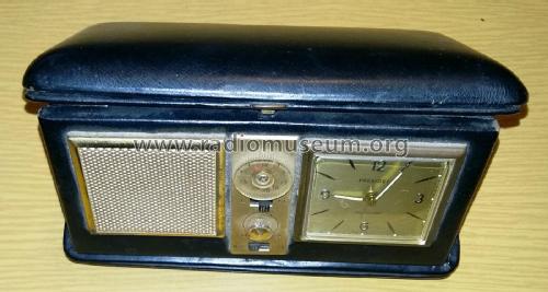
Radiolarm CTR625 Clamshell
Estyma; (wo?)
- Hersteller / Marke
- Estyma; (wo?)
- Jahr
- 1965 ??
- Kategorie
- Rundfunkempfänger (Radio - oder Tuner nach WW2)
- Radiomuseum.org ID
- 116062
- Anzahl Transistoren
- 6
- Halbleiter
- Hauptprinzip
- Superhet allgemein; ZF/IF 450 kHz
- Wellenbereiche
- Langwelle, Mittelwelle (LW+MW).
- Betriebsart / Volt
- Trockenbatterien / 9 Volt
- Lautsprecher
- Dynamischer (permanent) Ovallautsprecher / Ø 5 cm = 2 inch
- Belastbarkeit / Leistung
- 0.5 W (Qualität unbekannt)
- Material
- Metallausführung
- von Radiomuseum.org
- Modell: Radiolarm CTR625 [Clamshell] - Estyma; wo?
- Form
- Kleines Reisegerät oder «Taschengerät» < 20 cm.
- Abmessungen (BHT)
- 170 x 100 x 100 mm / 6.7 x 3.9 x 3.9 inch
- Bemerkung
-
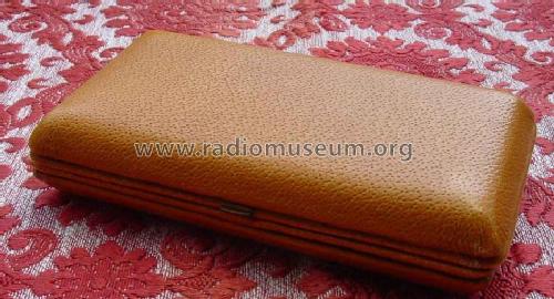
Reisewecker mit Radioalarm. Das Gehäuse ist Metall und Verkleidung aus echtem Leder. Der Wecker ist mechanisch.
The mechanical Clock part is German made in a real leather covered metal frame case. The radio part is a Hong Kong type (hence Empire Made and British patents). A similar clock movement is used in many "Alarm only" folding travel clocks of German make, including Estyma branded models. In this model a small switch is added to the clock mechanism to operate the radio part.
Battery is a PP3
The exact same model number, chassis and clock is used for a "book" styled case, Radiolarm CTR625 Radio Times Book
- Nettogewicht
- 0.5 kg / 1 lb 1.6 oz (1.101 lb)
- Datenherkunft
- - - Data from my own collection
- Autor
- Modellseite von Jozef Brughmans † angelegt. Siehe bei "Änderungsvorschlag" für weitere Mitarbeit.
- Weitere Modelle
-
Hier finden Sie 2 Modelle, davon 2 mit Bildern und 0 mit Schaltbildern.
Alle gelisteten Radios usw. von Estyma; (wo?)
Sammlungen
Das Modell Radiolarm befindet sich in den Sammlungen folgender Mitglieder.
Forumsbeiträge zum Modell: Estyma; wo?: Radiolarm CTR625
Threads: 1 | Posts: 1
The centre of both knobs (Tuner and volume) have "brass" colour anodised aluminium "brights". Use a sharp knife/scapel/craft to lever them off. They are only lightly glued and can be reattached with a piece of double sided tape or a small dab of general purpose glue applied with a match or cocktail stick.
The centre screws can be removed and the knobs pulled off.
Radio
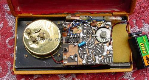
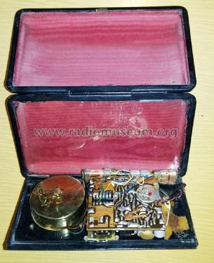
Remove rear battery cover and optionally unsolder alarm wires from PCB (note locations) and speaker wires from speaker. The cover fixing shaft unscrews from the loudspeaker magnet. Put the band and alarm switches at MW and Auto and lift out the PCB. It is hooked on to chassis at clock side.
Faults: Dry joints or even unsoldered component leads. There are 3 x IFT cores (single tuned) and one oscillator core for MW & LW. There should be no reason to adjust the IFTs. The osc core is probably best adjusted for peak RF sensitivity (rock tuning) about 600KHz on MW or "best" UK R4 on 198kHz LW (close to 20 mark). Unless experienced the alignment is best left alone.
Clock
Remove the knobs (winder clockwise as it's reverse thread, the other two pull off). Undo the three small screws at centre of rear cover and wiggle off carefully taking care of Alarm wires.
Faults: Dirt and internal screws coming loose. Don't use ordinary oil on clocks! You can wash off dirt with IPA, Methylated spirit or even surgical spirit. Possibly use the tinyist amount of specific watch oil or WD40, but nowhere near the balance wheel.
Reassembly
Basically reverse of disassembly. Don't apply glue direct to knobs but a tiny dab via a match stick or cocktail stick. You can pick up the "brights" with a damp finger tip and press down on knob after the set is reassembled.
The set is actually quite sensitive, but a little noisy. It's a conventional "Hong Kong" 1960s 6 transistor + diode shirt pocket type of PNP Germanium transistors ("2SA" types) with a subminature phase splitter driver transformer and output transformer.
- Mixer Osc with RF tuning on MW & LW ferrite rod coils and a single L.O. coil with extra capacitor on LW. 1st tuned IFT on collector.
- 2 x IF amps Collector tuned only
- diode detector, if there is AGC, it's simply the audio detector filtered.
- Transistor preamp/transformer driver
- Push pull 2 x transistors with output transformer. Class B.as it's very distorted if one transistor isn't connected!
Michael Watterson, 18.Sep.12

