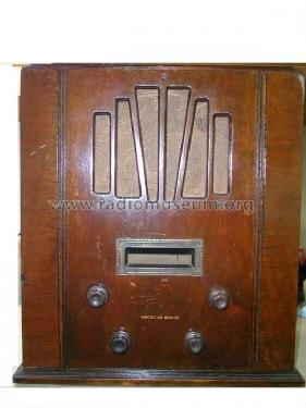
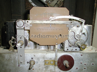
- Produttore / Marca
- United American Bosch (Magneto Corporation); Springfield (MA)
- Anno
- 1933
- Categoria
- Radio (o sintonizzatore del dopoguerra WW2)
- Radiomuseum.org ID
- 64017
-
- alternative name: American Bosch Magneto
- Brand: Essex
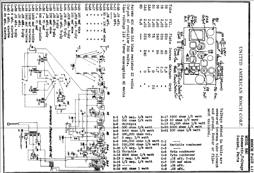
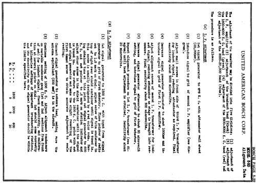
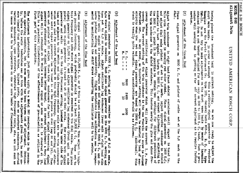
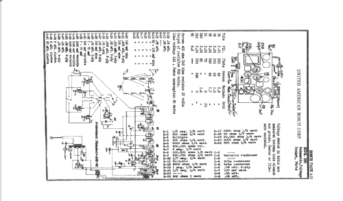
Clicca sulla miniatura dello schema per richiederlo come documento gratuito.
- Numero di tubi
- 7
- Principio generale
- Supereterodina (in generale); ZF/IF 456 kHz
- N. di circuiti accordati
- 9 Circuiti Mod. Amp. (AM)
- Gamme d'onda
- Onde medie (OM) e più di 2 gamme di onde corte (> 2 x OC).
- Tensioni di funzionamento
- Alimentazione a corrente alternata (CA) / 115 Volt
- Altoparlante
- AP elettrodinamico (bobina mobile e bobina di eccitazione/di campo)
- Materiali
- Mobile in legno
- Radiomuseum.org
- Modello: 360 - United American Bosch Magneto
- Forma
- Soprammobile verticale (sviluppato in altezza; no cattedrale, sin decorazioni).
- Fonte esterna dei dati
- Ernst Erb
- Fonte dei dati
- The Radio Collector's Directory and Price Guide 1921 - 1965
- Riferimenti schemi
- Rider's Perpetual, Volume 4 = ca. 1934 and before
- Letteratura / Schemi (1)
- -- Schematic
- Altri modelli
-
In questo link sono elencati 415 modelli, di cui 166 con immagini e 276 con schemi.
Elenco delle radio e altri apparecchi della United American Bosch (Magneto Corporation); Springfield (MA)
Discussioni nel forum su questo modello: United American: 360
Argomenti: 2 | Articoli: 12
I have some further information about the 2007 thread concerning the values of voltage dividing resistor R15 in the American Bosch model 360. A voltage dividing calculator can be found on this page:
www ohmslawcalculator.com/voltage-divider-calculator
This is a good tool especially for guys like me with no formal electrical engineering training. To determine the voltage at any tap point (to ground) in the voltage divider, you plug in the starting voltage (the voltage at the previous tap to the one you want to measure), the value of the resistor just upstream from the tap point, and the value of the resistor just after the tap point.
The R15 divider starts with a voltage of 240 which supplies the plate of the second I.F. 58 tube, as well as the screen and plate of the 2A5, among other circuits. We first need to step that down to 220 volts to supply the plates of the 58 first detector and 58 first I.F. tubes. According to the calculator, a 1.8k resistor followed by a 20k resistor, steps the 240 down to 220 almost perfectly at the second tap. (On my model 360, a repair tech had replaced this first divider with a 2k. All original R15 dividers are open on my set.)
Next, we need to drop the 220 volts down to 95 volts to supply the screens of both 58 I.F. tubes. Using trial and error, with 220 now as the starting voltage and the 20k as the upstream resistor, a value of 15k for the third resistor drops the voltage at tap 3 almost perfectly to 95 volts.
Now, we need to drop the 95 volts down to 40 volts to supply the screen of the first detector 58 tube. With 95 as the new starting voltage, and 15k as the upstream resistor, trial and error determines a value of 12k for resistor 4 produces a voltage of 40 at tap number 4 within a couple of volts.
Finally, we need to step the 40 volts down to as close to 0 as possible to ground the end of the circuit. Using 40 as the starting voltage, 12k as the upstream resistor, and "1 ohm" as a mock grounding value (the calculator won't let me use 0), you get a result of well under 1 volt, or for all intents and purposes, 0 volts.
So, according to this calculator, the values of R15 in the schematic should look like this:
- 12k - 15k - 20k - 1.8k - (current flow from right to left)
voltages at each tap point (represented by the dashes)
0v, 40v, 95v, 220v, 240v
I am still a ways off in the restoration of my set (my second model 360 restoration) but if you don't get a followup from me after several months, assume that these voltages worked out perfectly. I am planning to use 2 watt resistors for all the values just to be safe.
Jeffrey Gill, 16.Jan.16
Who can help me?
I have one radio Bosch 360W with the problem doesn't oscillate in any wave. He had several problems, among the ones which, without audio already resolved. Now I need to solve this, or be. The circuit oscillation doesn't work. This radio have the resistance (R15), tension division, one of the which, I designated it the 2.ª ( see fig.1), it is interrupted.
Please, anybody know how to inform which the value of the resistance? It is that in it part catalogue, only have the reference and in the designation "multiple resistance”. The resistance that is interrupted it the one that will give tensions to the grill of the 1.ª and 2.ª tube’s. Already changed the same ones, 56 and 58. I already tried to put several resistances, of values between 200k ohms and 750k ohms, but without result.
(Fig.1)
.jpg)
See schematic complet
(Fig.2)
forumdata/users/3656/BOSCH_360W_usa.jpg
Thank's for your's help's
Best Regard's
Júlio Branco
Allegati
- BOSCH_360W_cut_usa. (44 KB)
- BOSCH_360W_cut_usa. (44 KB)
Júlio Branco, 15.May.07
