Satellite Solid State FM Tuner to Eight 8-Track HD-1404
Unknown - CUSTOM BUILT: Japan
- Paese
- Giappone
- Produttore / Marca
- Unknown - CUSTOM BUILT: Japan
- Anno
- 1970 ??
- Categoria
- Radio (o sintonizzatore del dopoguerra WW2)
- Radiomuseum.org ID
- 333716
Antenna socket at the right side.
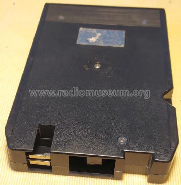
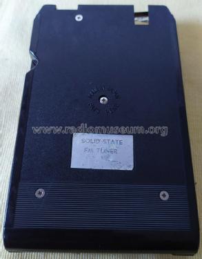
Made in Japan, Pats. Pending
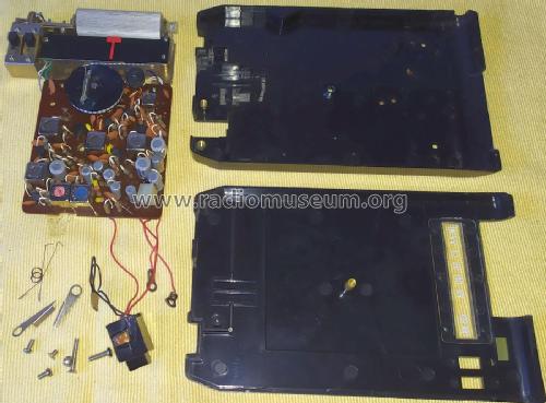
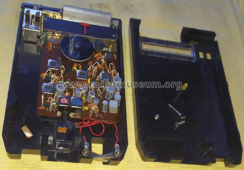
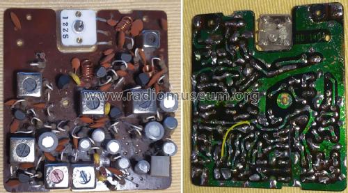
General assemblies view.
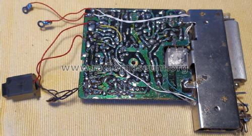
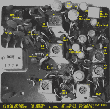
Chassis PCB copper side, ref. HD-1404
Clicca sulla miniatura dello schema per richiederlo come documento gratuito.
- Numero di transistor
- 9
- Principio generale
- Supereterodina con stadio RF
- N. di circuiti accordati
- 9 Circuiti Mod. Freq. (FM)
- Gamme d'onda
- Solo modulazione di frequenza (FM)
- Tensioni di funzionamento
- Fornita mediante altra unità o unità principale. / 12 Volt
- Altoparlante
- - Per cuffie o amplificatori esterni
- Materiali
- Plastica (non bachelite o catalina)
- Radiomuseum.org
- Modello: Satellite Solid State FM Tuner to Eight 8-Track HD-1404 - Unknown - CUSTOM BUILT: Japan
- Forma
- Chassis o in scatola da montaggio
- Dimensioni (LxAxP)
- 100 x 24 x 165 mm / 3.9 x 0.9 x 6.5 inch
- Annotazioni
-
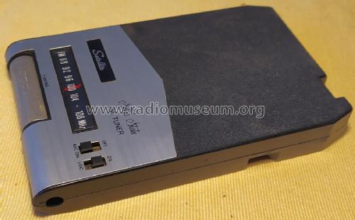
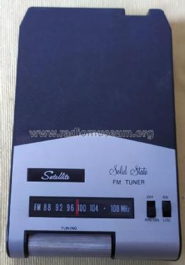
This is a FM Tuner adapter encapsulated inside a 8-Track cartridge. It is a FM Radio to 8-Track player converter.
Main specifications
- Frequency coverage: FM 88 - 108 MHz
- AFC OFF/ON, selectable
- DX/Local, selectable
- FM Mono
- FM antenna input socket at the front right side
- Audio output: Magnetic coupling with a dual channel write tape head wired in Mono
- Power Supply: 12VDC nominal using the 8-Track Player auto-change track sensor
Made in Japan
- Autore
- Modello inviato da Jose Mesquita. Utilizzare "Proponi modifica" per inviare ulteriori dati.
- Altri modelli
-
In questo link sono elencati 1141 modelli, di cui 1004 con immagini e 96 con schemi.
Elenco delle radio e altri apparecchi della Unknown - CUSTOM BUILT: Japan
Collezioni
Il modello Satellite Solid State FM Tuner to Eight 8-Track fa parte delle collezioni dei seguenti membri.
Discussioni nel forum su questo modello: Unknown - CUSTOM: Satellite Solid State FM Tuner to Eight 8-Track HD-1404
Argomenti: 1 | Articoli: 1
This is typical cheap Japanese design from the 70´s, using Japanese components and workmanship. Still, it uses a high number of RF stages to offer high sensitivity and selectivity required to be used inside a car.
The antenna signal is injected to the antenna socket located at the front right side of the 8-Track cartridge that encapsulates the FM radio tuner, and passed thru a canned band pass filter to the tuned RF Front-End (Q1). The signal is then passed to the Mixer stage (Q2) working with the Local Oscillator (Q3). Q1, Q2, and Q3 are medium gain 2SC829B devices.
The IF signal is then amplified thru no less than four stages: IFT1 to Q4 to IFT2 to Q5 to IFT3 to Q6 to IFT4 to Q7 to IFT5 to IFT6 and D4/D5 decoder. AGC circuit is handled by a RC and diode network.. Selectable AFC is handled by a varicap (D1). Q4 to Q7 are high gain 2SC829C devices. Canned IFT1 to IFT4 transsformers have the reference "IF001" in black, while IFT5 is a "ID001" in pink, and IFT6 is a "ID002" in blue.
The large output audio signal from the FM decoder is then used to feed a single stage audio amplifier (Q8) in common emitter setup whose collector is resistor loaded, and the output signal is capacitively coupled (Co) to drive the output write magnetic head used to transfer the audio signal to the 8-track player's read magnetic head where this unit is inserted into. Q8 is amedium current 2SB175A. Co is a 10uF/6V electrolytic capacitor. The dual channel write head have the two coils wired in series for Mono for a total resiste load of 2K3 (couldn't measure the inductance at this time).
Other FM to 8-track adapters use a 9V dry battery installed in a dedicated battery compartment. No so in this model. The battery solution looks to be a simple solution, but the dial lamp would deplet it faster than desirable.
In this model, the power supply uses the 12VDC nominal value collected at thee 8-Track Player auto-change track sensor using two spring loaded condutive levers, and a Stanley selennium bridge rectifier (B1) ensures that the correct polarity is applied to the input capacitor (Cfi). This design use positive ground. As the sellennium bridge tipycally presents a high voltage drop of around 2V, about -10V are present at the input capacitor. A conventional series regulator using a Zenner diode as ferenece voltage (Dz) and a transistor (Q9) would supply the nominal -6V Vdd tension to the circuit, filtered by a output capacitor (Cfo).
As I see it, the above power supply design implementation has a flaw, at least in my unit.
Q9 is a medium current 2SB176. Dz is a JRC 1S334 diode (8.7V typical). Cfi is a 30uF/15V. But Cfo is a 100uF/6V electrolytic capacitor, and it will be working at its upper limits. Additional bypass capacitors are also rated at 6V as well. These components looks to be the original devices as its PCB solder pads looks untouched.
I would have specified a lower reference voltage Zenner to make sure the Vdd tension would never exceed the maximum working voltage of the capacitors.But as this unit is a collector model, it will stay as it is.
Jose Mesquita, 15.Nov.21