unknown Spark Transmitter
Unknown to us - Worldwide
- Land
- Weltweit
- Hersteller / Marke
- Unknown to us - Worldwide
- Jahr
- 1900 ??
- Kategorie
- Morse-Geräte & TTY, RTTY, TDD etc.
- Radiomuseum.org ID
- 238588
- Hauptprinzip
- Sender
- Betriebsart / Volt
- Akku und/oder Batterie / 6-12 Volt
- Belastbarkeit / Leistung
- 1 W (Qualität unbekannt)
- von Radiomuseum.org
- Modell: unknown Spark Transmitter - Unknown to us - Worldwide
- Form
- Diverse Formen, unter Bemerkung beschrieben.
- Abmessungen (BHT)
- 130 x 200 x 130 mm / 5.1 x 7.9 x 5.1 inch
- Bemerkung
-
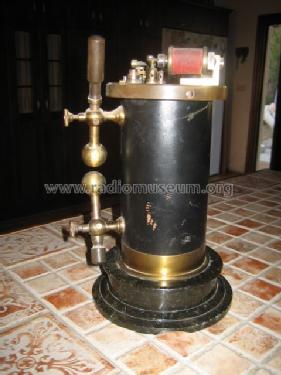
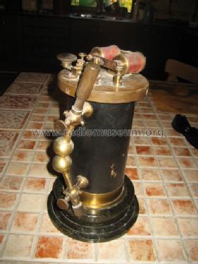
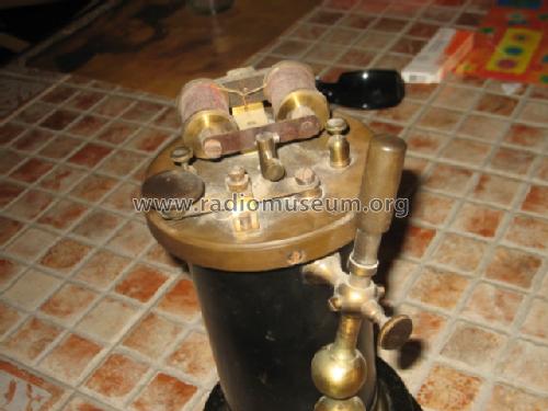
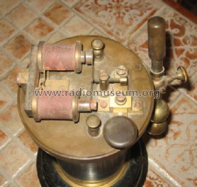
This small spark transmitter was probably used at ships as a test signal to adjust the receiver detectors. It does not have a resonating circuit but can be connected to a resonating antenna just as the Marconi emergency transmitters. The power though is too small to be a communication unit. When connected at a 1 MHz resonating circuit with 1000 pF capacitor, the peak power is approx. 2 kW and the avarage power is approx. 1 Watt with a pulse repetition frequency of 100 Hz. connected at a 6V lead acid battery.
The body is carton holding the coils completely potted with bees wax. The base is heavy stone nicely elaborated.
- Nettogewicht
- 3.1 kg / 6 lb 13.3 oz (6.828 lb)
- Autor
- Modellseite von Nicolaas van Dijk angelegt. Siehe bei "Änderungsvorschlag" für weitere Mitarbeit.
- Weitere Modelle
-
Hier finden Sie 823 Modelle, davon 756 mit Bildern und 29 mit Schaltbildern.
Alle gelisteten Radios usw. von Unknown to us - Worldwide
Sammlungen
Das Modell unknown Spark Transmitter befindet sich in den Sammlungen folgender Mitglieder.
Forumsbeiträge zum Modell: Unknown to us -: unknown Spark Transmitter
Threads: 2 | Posts: 11
Dear fellow Wireless enthusiasts!
Since this little transmitter has been brought to my attention, I couldn't help but wonder who built it.
The workmanship looks quite excellent, materials are good (heavy brass, ebonite, stone base), too good for a toy set. But it is obviously not suitable for long-range communication, judging from the tiny interruptor on top.
It has been sugested this might be a demonstration set. But from which maker, and demonstrating which system of wireless telegraphy?
In the Elektrotechnische Zeitschrift (ETZ), No. 45 from Nov. 1904, there is a report on the French system of wireless telegraphhy by Rochefort. The transmitter instantly reminded me of this set.
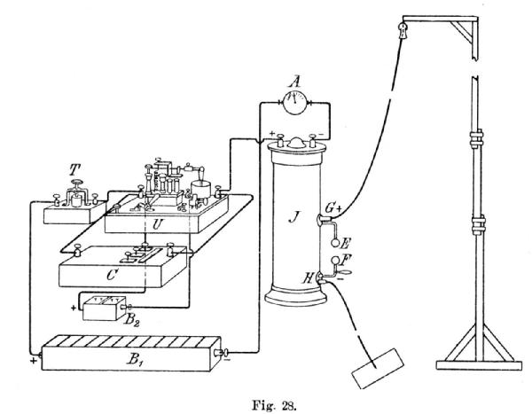
This is a commercial type of equipment. It's an untuned Marconi transmitter. There is a separate mercury interruptor U, kept in constant operation by battery B2. The optimum number of interruptions is said to 24 to 30 per second. The key T with platinum tip and mercury contact closes the circuit from battery B1 (24V 100Ah) through the interruptor with condenser C in parallel, to induction coil J. The spark gap terminals are 2cm in diameter. A spark of 5 to 10mm length is employed.
The receiver looks as follows:
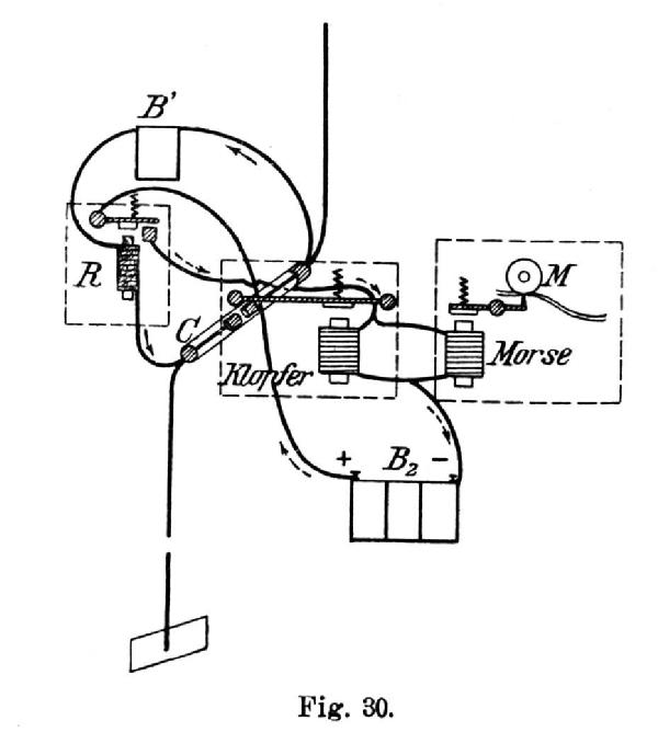
A very basic coherer receiver and tapper with separate relay of 1000 Ohms, and morse inker. No tuned circuits are to be found beside the antenna, no chokes or polarizing cells to suppress the effects of the local relay contact spark.
But wait, the coherer is special. Rochefort designed a magnetically adjustable coherer.

Two short segments of iron tubing are included inside the glass tube. They are traversed but not contacted by a piece of copper wire, which is connected to the second coherer terminal. The space in between the pole pieces is filled with soft iron filings. In the receiver assembly, there is a magnet placed above the coherer, which aids in adjusting coherer sensitivity.
The system Rochefort was demonstrated to the k.u.k Austrian Navy in 1902. The receiver assoioated with the equipment is illustrated in Sifferlinger's "Auslaufen verspricht Erfolg" (2000). The adjustable magnet can be seen top left.

The Rochefort equipment was reported to be working reliably over a range of 40km and more.
In the 1904 article from ETZ (above) there is information that Rochefort had by then used a tuned circuit after Oudin (effectively a Braun closed circuit) on the transmitter end, which was not yet used during the Austrian trials.
After extensive tests, the equipment by AEG/Slaby - Arco and Braun/Siemens & Halske was introduced into the Austrian Navy.
Marconi would have been a contender, but the Marconi company was reluctant to actually sell their apparatus, as their business model revolved around leasing apparatus and collecting regular fees.
From what information I have gathered, I suppose the upright spark transmitter in question is a Rochefort demonstration set.
Yours,
Nikolaus Löwe
Nikolaus Löwe, 20.Nov.22
I uploaded foto's from a small unknown spark transmitter with some information in page with id 238588.
I did try to put the link in this text, but was unable to do that. Typing it does not work
The transmitter may be a signal source used at ships to adjust the detectors of the receiver. The power is too small for being a communication unit. Connected at 6 volts and connected at a 1 MHz resonance circuit with a 1000 pF capacitor, the avarage power is approx. 1 Watt while the peak power is approx 2 kW
Is there someone that can give some more information about this device?
Kind regards
Nico
Anlagen
- spark transmitter 001 (60 KB)
Nicolaas van Dijk, 19.Jul.13
