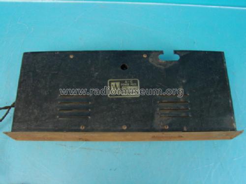
A-C Power Pack (Battery Eliminator) Style B
Webster Co., The, Webster-Chicago, Webcor; Chicago (IL)
- Land
- USA
- Hersteller / Marke
- Webster Co., The, Webster-Chicago, Webcor; Chicago (IL)
- Jahr
- 1928
- Kategorie
- Strom-Versorgung oder Spannungsstabilisator
- Radiomuseum.org ID
- 245662
-
- Marke: Webcor

Radio Engineering, June 1928, p.9
- Anzahl Röhren
- 1
- Röhren
- Wellenbereiche
- - ohne
- Betriebsart / Volt
- Wechselstromspeisung / 110 Volt
- Lautsprecher
- - - Kein Ausgang für Schallwiedergabe.
- Material
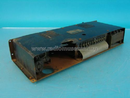
- Metallausführung
- von Radiomuseum.org
- Modell: A-C Power Pack Style B - Webster Co., The, Webster-
- Form
- Chassis - Einbaugerät
- Abmessungen (BHT)
- 2.75 x 6.13 x 16 inch / 70 x 156 x 406 mm
- Bemerkung
-
Designed to supply all A.C. and D.C. voltages as well as all grid biases for all makes of receivers using A.C. tubes.
Available in two styles.
The Webster AC-Power Pack probably uses an UX280 as rectifier.
- Originalpreis
- 32.50 $
- Literaturnachweis
- Radio Engineering (Advertisement June 1928, p.9)
- Autor
- Modellseite von Daniel Kolbach angelegt. Siehe bei "Änderungsvorschlag" für weitere Mitarbeit.
- Weitere Modelle
-
Hier finden Sie 440 Modelle, davon 208 mit Bildern und 363 mit Schaltbildern.
Alle gelisteten Radios usw. von Webster Co., The, Webster-Chicago, Webcor; Chicago (IL)
Sammlungen
Das Modell A-C Power Pack (Battery Eliminator) befindet sich in den Sammlungen folgender Mitglieder.
Forumsbeiträge zum Modell: Webster Co., The,: A-C Power Pack Style B
Threads: 1 | Posts: 2
I have been working on this thing for a few days now. It has been very difficult as the color of the cables are faded away and you have to follow each connection by hand. It doesn’t help that they used some kind of glue to hold everything together and now that is crumbling.
I have tested the two main transformers, the primaries seem to be ok. I only applied 10v to them and measure the secondary. I used a little math to calculate the final output. So far this is what I have found out:
T1 (T1 and T2 are the two main transformers), primary winding has 4 taps on it, I calculated that they are: 5.5v, 43.5v, 78.7v and 92.1v. The taps are connected directly to back terminal screws. The secondary as 3 leads with 5.5v and a center tap (sorry I drew the attachment wrong)
T2 has a secondary with 3 leads and the go to the pins of the socket. If my calculations are correct then at 115v on the primary the outside leads on the secondary will be at 586v, the tap in the middle produces 293v to each side.
I have a few questions:
- Does anyone have seen the configuration described for T1? With all those taps from the primary going into the connecting panel.
- Normally in the rectifiers circuits that I have seen, it should be a connection between the two transformers. Or this make sense?
- With the voltages that I described for T2, would UX280 will be a candidate for this?
I’m still working on creating a schematic for this, takes time as I have to redraw the whole thing when it becomes too tangle.
Thanks
Daniel Kolbach
Anlagen
- Diagram (220 KB)
Daniel Kolbach, 01.Jan.14