Hearing Aid for the deaf
Wireless World; London
- Pays
- Royaume Uni
- Fabricant / Marque
- Wireless World; London
- Année
- 1936
- Catégorie
- Boîte de construction (composants et manuel) ou instructions
- Radiomuseum.org ID
- 353304
Cliquez sur la vignette du schéma pour le demander en tant que document gratuit.
- No. de tubes
- 2
- Principe général
- Amplification audio
- Gammes d'ondes
- - sans
- Particularités
- Aide auditive
- Tension / type courant
- Piles sèches / 2 & 45 Volt
- Haut-parleur
- - Pour casque ou amplificateur BF
- Matière
- Boitier en bois
- De Radiomuseum.org
- Modèle: Hearing Aid for the deaf - Wireless World; London
- Forme
- Portative > 20 cm (sans nécessité secteur)
- Dimensions (LHP)
- 7.25 x 5.7 x 4.75 inch / 184 x 145 x 121 mm
- Remarques
-
Hearing Aid for the deaf
Two Valve Amplifier Unit by T. S. Littler, M.Sc. Ph. D
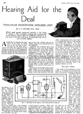
The small portable hearing aid described in this article embodies a carbon microphone combining high sensitivity with a good frequency response while the amplification afforded by its two valves is such that it will prove of considerable help even in cases of serious deafness.
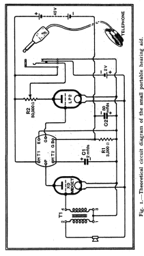
The circuit of the hearing aid is given in Fig. 1. It consists of a two-valve amplifier with parafeed coupling between the two stages. The first valve used is a Hivac Midget Type XD, the anode of which is connected the tapped resistance of the parafeed unit, the tapping HT2 being used for anode decoupling through the electrolytic condenser C1. For the second stage, an LP2 valve has been used as an extremely efficient small power valve combining high sensitivity with very small power consumption.
A midget valve can be used in this stage if desired, but, of course, the effective amplification will be less. The automatic bias of about 1½ volts is used on the second valve, R1 being the bias resistance shunted by an electrolytic low voltage condenser, C2, of 50 microfarads. For the first valve the fall of potential along the filament is used to maintain negative bias on its grid, the grid return of the microphone transformer T1 being connected to the negative end of the filament. For intensity control, a 50,000-ohm potentiometer is connected to the anode of the last valve, and the telephone output is connected across the variable tapping. A double-circuit automatic jack is used for operating the instrument so that the insertion of the telephone plug switches on the low-tension supply at the same time. The telephone used is a small disc receiver with a headband, but modifications of this may be made to suit the user. For example, a pair of standard telephone receivers, or piezo-electric receivers, could be used, but in the case of the latter modification, care must be taken to insert a condenser in one of the output connections to prevent a DC voltage from being applied across the batteries in position. If alternative sizes of batteries are used the size of this block must be altered accordingly.
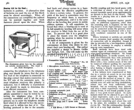
When all the connections are completed the cabinet can be screwed together and hook fasteners placed upon the door. When connecting the telephone to the telephone plug care should be taken that the positive lead of the telephone is connected to the plug contact that makes a connection to the HT side of the automatic jack. In most telephone receivers this polarity is indicated, but if difficulty is experienced a test should be made to determine the most efficient connection.
Peto Scott produced two commercial models from this design.
- Schémathèque (1)
- Wireless World (The), London (WW, 79) (Apr 17, 1936, Page 380 - 382)
- Auteur
- Modèle crée par Gary Cowans. Voir les propositions de modification pour les contributeurs supplémentaires.
- D'autres Modèles
-
Vous pourrez trouver sous ce lien 7 modèles d'appareils, 5 avec des images et 6 avec des schémas.
Tous les appareils de Wireless World; London


