12-S-265 Ch=1204
Zenith Radio Corp.; Chicago, IL
- Land
- USA
- Hersteller / Marke
- Zenith Radio Corp.; Chicago, IL
- Jahr
- 1937/1938
- Kategorie
- Rundfunkempfänger (Radio - oder Tuner nach WW2)
- Radiomuseum.org ID
- 67326
-
- anderer Name: Chicago Radio Lab


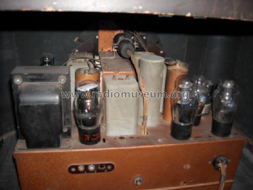
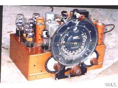
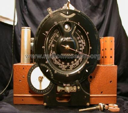
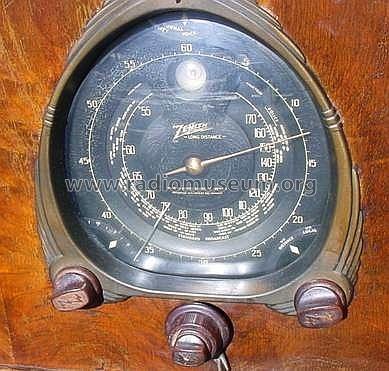
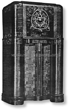
Zenith Model 12-S-265 (1937) Copy from Ebay

Copy gen. von John Goller Radio Attic
eBay.com 130655475943 seller: bm071

eBay.com 130655475943 seller: bm071
By courtesy of William Kendrick, USA

eBay seller: tnorthup (USA). #6612636068

eBay seller: tnorthup (USA). #6612636068

eBay seller: tnorthup (USA). #6612636068
eBay seller: tnorthup (USA). #6612636068
eBay.com 130655475943 seller: bm071
Ebay USer danteboy518 Item 320882243409

Ebay USer danteboy518 Item 320882243409

Ebay USer danteboy518 Item 320882243409

Ebay USer danteboy518 Item 320882243409

Ebay USer danteboy518 Item 320882243409

Ebay USer danteboy518 Item 320882243409


Klicken Sie auf den Schaltplanausschnitt, um diesen kostenlos als Dokument anzufordern.
- Anzahl Röhren
- 12
- Hauptprinzip
- Super mit HF-Vorstufe; ZF/IF 456 kHz
- Anzahl Kreise
- 7 Kreis(e) AM
- Wellenbereiche
- Mittelwelle, Kurzwelle und Tropenband.
- Betriebsart / Volt
- Wechselstromspeisung / 115 Volt
- Lautsprecher
- Dynamischer LS, mit Erregerspule (elektrodynamisch) / Ø 12 inch = 30.5 cm
- Belastbarkeit / Leistung
- 15 W (Qualität unbekannt)
- Material
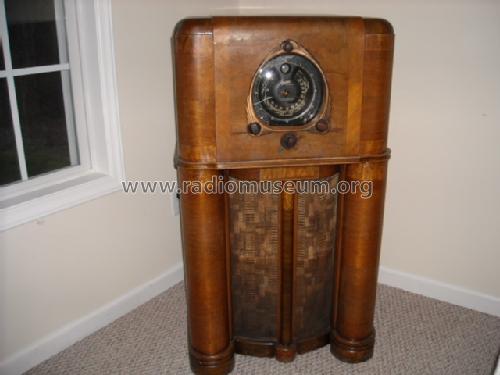
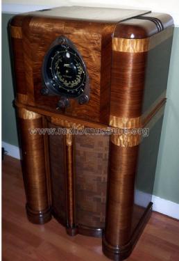
- Gerät mit Holzgehäuse
- von Radiomuseum.org
- Modell: 12-S-265 Ch=1204 - Zenith Radio Corp.; Chicago,
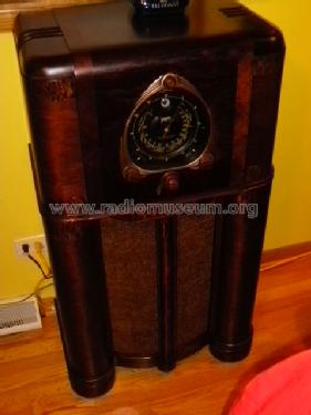
- Form
- Standgerät: allgemein.
- Abmessungen (BHT)
- 25 x 43 x 15 inch / 635 x 1092 x 381 mm
- Bemerkung
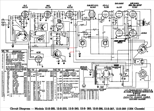
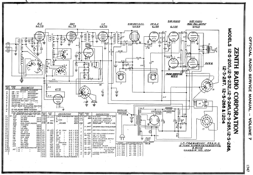
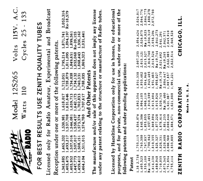
- The schematic diagram got corrections (red). These lines are already missing in the Zenith drawing as well as in Riders and in Beitman.
Bunis predates by one year. This may be based on Zenith 1937 advertising "Preview of new products" in "Blast of the Past". And usually the season started mostly the previous year to get the X-mas sales.
- Originalpreis
- 140.00 $
- Datenherkunft extern
- Ernst Erb
- Schaltungsnachweis
- Rider's Perpetual, Volume 8 = 1937 and before
- Literaturnachweis
- Collector's Guide to Antique Radios 4. Edition
- Literatur/Schema (1)
- Zenith Radio The Glory Years 1936-1945
- Literatur/Schema (2)
- Pre-War Consoles
- Weitere Modelle
-
Hier finden Sie 4519 Modelle, davon 4111 mit Bildern und 3656 mit Schaltbildern.
Alle gelisteten Radios usw. von Zenith Radio Corp.; Chicago, IL
Sammlungen
Das Modell 12-S-265 befindet sich in den Sammlungen folgender Mitglieder.
Forumsbeiträge zum Modell: Zenith Radio Corp.;: 12-S-265 Ch=1204
Threads: 3 | Posts: 3
Correction made (red). These lines are already missing in the Zenith drawing as well as in Riders and in Beitman. Schematic with the erroneous correction is deleted.
Konrad Birkner † 12.08.2014, 22.Aug.10
I am currently restoring a Zenith 12S265. In the center of the schematic that the radio museum lists shows a capacitor called "C". The schematic shows this capacitor being connected to R8. I believe this to be in error. The 12S265 radio I have has this capacitor connected to the first line directly to the right. The line to the right connects to the screen grids of the I.F. amplifier (pin 4 of the 6K7G) The 1st detector (pin 4 of the 6L7G) and to the R.F amplifier (pin 4 of the 6K7G). The line also connects to the positive side of capacitor C25 which connects to the junction of the two 11 Kohm candohm wire wound resistors. This capacitor called "C" on the prints should be called C7 which in my radio and shown on the schematic is a .1 microfarad 400 V.D.C part # 22-170 paper tubular capacitor. Also R8 should be connected to R2 found at the bottom of the secondary winding I. F. transformer #5 and connected to C9. I believe coming off of this R2 resistor is the A.V.C. voltage which goes out to the R.F. amplifier 1st detector, the tuning eye tune, (6T5) and the 6K7 I.F. amplifier.
Hope this will be helpfull to someone!
John
John Bartholomew, 22.Aug.10
In restoreing this particular radio I found that the two tuning drive belts had to be replaced. After doing much searching I found rubber O-rings from Mercury Marine that worked perfectly. The part number for the large one is 25-70937,[ I.D. is 3 1/2 inch---width is .135 inch ]. The part number for the small one is 25-20863,[ I.D. is 2.625 inch.--- width is .135 inch ]. The website for Mercury Marine is, www.mercurymarine.com.
Ross Hoff, 22.Sep.09