- Pays
- Etats-Unis
- Fabricant / Marque
- Admiral (brand) Continental Radio & Television Co.; Chicago, IL
- Année
- 1951 ?
- Catégorie
- Radio - ou tuner d'après la guerre 1939-45
- Radiomuseum.org ID
- 31258
-
- alternative name: Continental Radio & TV


Q = ebay objnr : 280071833704

Q = ebay objnr : 280071833704
Q = ebay objnr : 280071833704
Q = ebay objnr : 280071833704
Q = ebay objnr : 280071833704

Q = ebay objnr : 280071833704

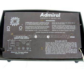
RECONSTRUCTED LABEL
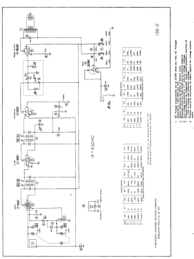
Cliquez sur la vignette du schéma pour le demander en tant que document gratuit.
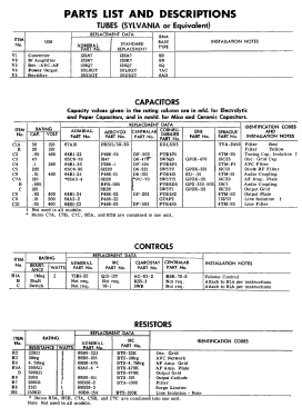
- No. de tubes
- 5
- Principe général
- Super hétérodyne (en général); FI/IF 455 kHz; 2 Etage(s) BF
- Circuits accordés
- 6 Circuits MA (AM)
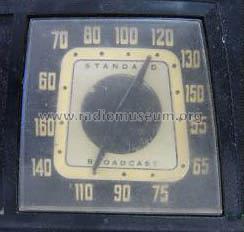
- Gammes d'ondes
- PO uniquement
- Tension / type courant
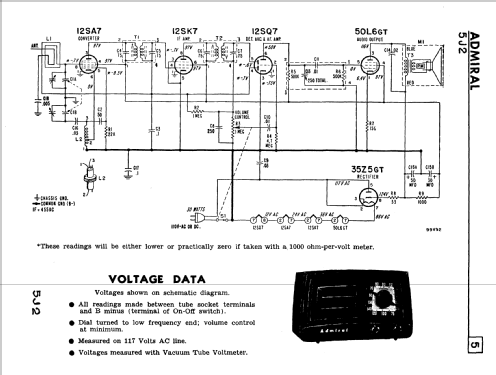
- Appareil tous courants (CA / CC) / 117V = 110 -120 Volt
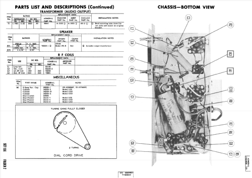
- Haut-parleur
- HP dynamique à aimant permanent + bobine mobile / Ø 5 inch = 12.7 cm
- Matière
- Plastique moderne (pas de bakélite, ni de catalin)
- De Radiomuseum.org
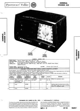
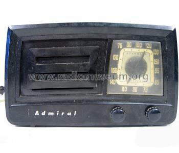
- Modèle: 5J21 Ch= 5J2 - Admiral brand Continental
- Forme
- Modèle de table générique
- Remarques
-
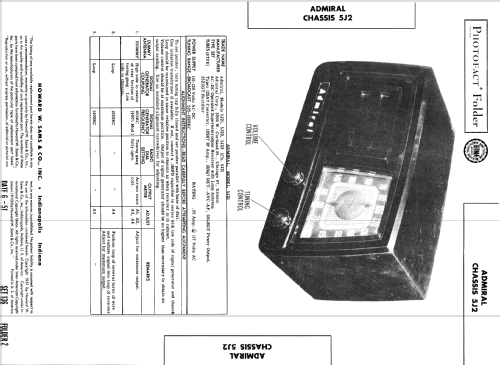
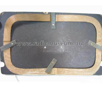
Admiral model 5J21 is an AC-DC operated superheterodyne receiver with loop antenna.
Color= Ebony, chassis 5J2 is identical to 5E2.
- Source extérieure
- Ernst Erb
- Source du schéma
- Beitman Radio Diagrams Vol. 11, 1951
- Schémathèque (1)
- Rider's Perpetual, Volume 22 = covering 1951
- Schémathèque (2)
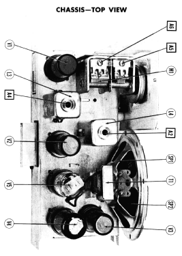
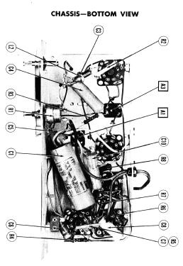
- Photofact Folder, Howard W. SAMS (Date 6-1951, Set 136, Folder 2)
- Schémathèque (3)
- Photofact Folder, Howard W. SAMS (Set 136, folder 2, dated 6-51)
- D'autres Modèles
-
Vous pourrez trouver sous ce lien 3229 modèles d'appareils, 1333 avec des images et 2599 avec des schémas.
Tous les appareils de Admiral (brand) Continental Radio & Television Co.; Chicago, IL
Contributions du forum pour ce modèle: Admiral brand: 5J21 Ch= 5J2
Discussions: 2 | Publications: 2
The Sams photofact with 136-2 on it at first glance on the screen looks like the 50L6 has a #1 pin connection however when enlarged/ printed it is an 8. The other schematics on the various iistings here have a #1 when enlarged or printed out. Also this schematic has the correct and easier to understand boxed in area for C7/R5 which is a combined Capacitor and resistor that looks like a 2x3 cm square flat capacitor. The boxed in area with it's individual parts diagrammed out allowed me to easily replace the combined part with 5 different resistors and capacitors .
Michael Saija, 15.Jun.19
The 50L6 tube has NO number 1 pin. The schematics show a 150 ohm resistor from pin 1 to chassis ground however in reality ( and it shows on the Sams photo's) the number 1 position on the socket is grounded to chassis. The 150 ohm resistor actually goes from the #8 pin to the #1 pin socket position and thence to chassis ground.
Michael Saija, 15.Jun.19